Table 2. data format (two’s complement) – Rainbow Electronics MAX1619 User Manual
Page 11
tems, since a second master could overwrite the com-
mand byte without informing the first master.
The temperature data format is 7 bits plus sign in two’s
complement form for each channel, with each data bit rep-
resenting 1°C (Table 2), transmitted MSB first. Measure-
ments are offset by +1/2°C to minimize internal rounding
errors; for example, +99.6°C is reported as +100°C.
Alarm Threshold Registers
Two registers store ALERT threshold limits, with high-
temperature (T
HIGH
) and low-temperature (T
LOW
) reg-
isters for the remote A/D channel. There are no
comparison registers for the local A/D channel. If either
measured temperature
equals or exceeds
the corre-
sponding alarm threshold value, an ALERT interrupt is
asserted. The power-on-reset (POR) state of the T
HIGH
register is full scale (0111 1111, or +127°C). The POR
state of the T
LOW
register is 1100 1001 or -55°C.
Two additional alarm threshold registers control the
OVERT output (see OVERT
Alarm Output
section), T
MAX
and T
HYST
. The POR state of T
MAX
is +100°C, and
T
HYST
is +95°C.
O
OV
VE
ER
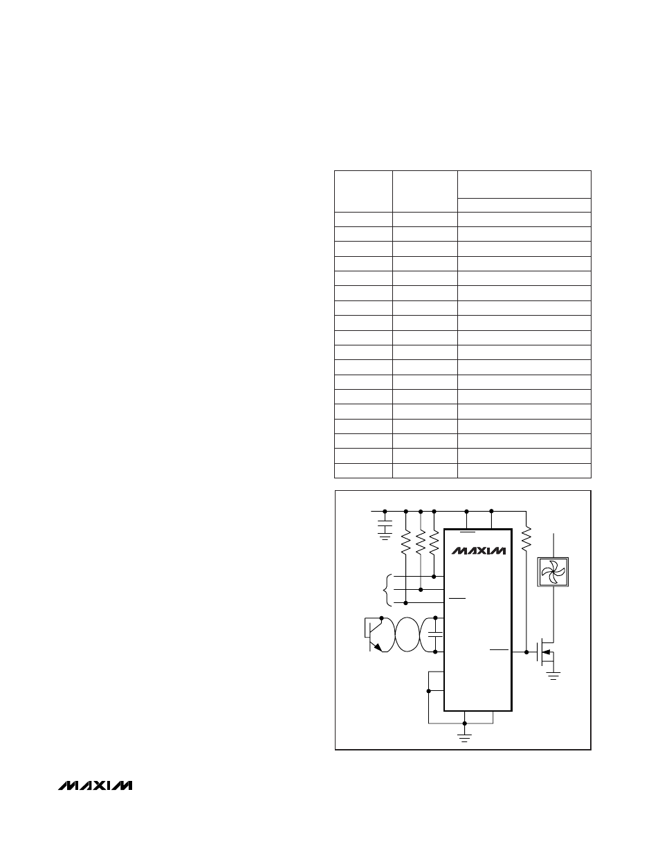
RTT Alarm Output for Fan Control
The OVERT output is an unlatched open-drain output that
behaves as a thermostat to control a fan (Figure 4). When
using the SMBus interface, the polarity of the OVERT pin
(active-low at POR) can be inverted via bit 5 in the config-
uration byte. OVERT’s current state can be read in the
status byte.
OVERT can also be used to control a fan without system
intervention. OVERT goes low when the remote tempera-
ture rises above T
MAX
and won’t go high again until the
temperature drops below T
HYST
. The power-up default
settings for T
MAX
and T
HYST
(+100°C and +95°C,
respectively) allow the MAX1619 to be used in stand-
alone thermostat applications where connection to an
SMBus serial bus isn’t required.
Diode Fault Alarm
There is a continuity fault detector at DXP that detects
whether the remote diode has an open-circuit condi-
tion. At the beginning of each conversion, the diode
fault is checked, and the status byte is updated. This
fault detector is a simple voltage detector; if DXP rises
above V
CC
- 1V (typical) due to the diode current
source, a fault is detected. Note that the diode fault
isn’t checked until a conversion is initiated, so immedi-
ately after power-on reset the status byte indicates no
fault is present, even if the diode path is broken.
MAX1619
Remote/Local Temperature Sensor with Dual-
Alarm Outputs and SMBus Serial Interface
______________________________________________________________________________________
11
DIGITAL OUTPUT
DATA BITS
0
111
1111
+127
+127.00
0
111
1111
0
111
1110
+126
+126.00
+127
+126.50
0
001
1001
0
000
0001
+1
+0.50
0
000
0000
0
000
0000
0
0.00
ROUNDED
TEMP.
(°C)
TEMP.
(°C)
0
+0.25
+25
+25.25
0
000
0000
0
000
0000
0
-0.50
1
111
1111
1
111
1111
-1
-1.00
-1
-0.75
1
110
0111
1
110
0111
-25
-25.50
1
100
1001
1
100
1001
-55
-55.00
0
-0.25
-55
-54.75
-25
-25.00
1
011
1111
1
011
1111
-65
-70.00
-65
-65.00
Table 2. Data Format (Two’s Complement)
SIGN
MSB
LSB
0
111
1111
+127
+130.00
MAX1619
SMBCLK
ADD0
ADD1
STBY
V
CC
PGND
+12V
GND
DXP
DXN
+3V TO +5.5V
SMBUS
SERIAL
INTERFACE
(TO HOST)
2N3904
SMBDATA
ALERT
OVERT
Figure 4. Fan Control Application