Single-ended ac-coupled input signal – Rainbow Electronics MAX1209 User Manual
Page 21
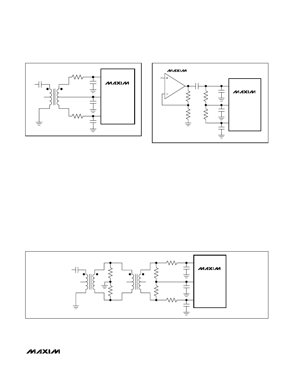
The circuit of
Figure
11 converts a single-ended input
signal to fully differential just as
Figure
10. However,
Figure
11 utilizes an additional transformer to improve
the common-mode rejection, allowing high-frequency
signals beyond the Nyquist frequency. The two sets of
termination resistors provide an equivalent 75
Ω termi-
nation to the signal source. The second set of termina-
tion resistors connects to COM, providing the correct
input common-mode voltage. Two 0
Ω resistors in series
with the analog inputs allow high IF input frequencies.
These 0
Ω resistors can be replaced with low-value
resistors to limit the input bandwidth.
Single-Ended AC-Coupled Input Signal
Figure
12 shows an AC-coupled, single-ended input
application. The MAX4108 provides high speed, high
bandwidth, low noise, and low distortion to maintain the
input signal integrity.
MAX1209
12-Bit, 80Msps, 3.3V IF-Sampling ADC
______________________________________________________________________________________
21
MAX1209
1
2
3
6
5
4
N.C.
V
IN
0.1
µF
T1
MINICIRCUITS
TT1-6 OR T1-1T
24.9
Ω
24.9
Ω
12pF
12pF
2.2
µF
INP
COM
INN
Figure 10. Transformer-Coupled Input Drive for Input
Frequencies Up to Nyquist
MAX1209
1
2
3
6
5
4
N.C.
N.C.
T2
MINICIRCUITS
ADT1-1WT
1
2
3
6
5
4
N.C.
V
IN
0.1
µF
T1
MINICIRCUITS
ADT1-1WT
0
Ω*
0
Ω*
5.6pF
5.6pF
2.2
µF
INP
COM
INN
110
Ω
0.1%
110
Ω
0.1%
75
Ω
0.5%
75
Ω
0.5%
*0
Ω
RESISTORS CAN BE REPLACED WITH LOW-VALUE
RESISTORS TO LIMIT THE BANDWIDTH.
Figure 11. Transformer-Coupled Input Drive for Input Frequencies Beyond Nyquist
MAX1209
5.6pF
5.6pF
2.2
µF
INP
COM
INN
24.9
Ω
24.9
Ω
100
Ω
100
Ω
0.1
µF
MAX4108
V
IN
Figure 12. Single-Ended, AC-Coupled Input Drive