Max1848, White led step-up converter in sot23, Detailed description – Rainbow Electronics MAX1848 User Manual
Page 6: Design procedure
MAX1848
Detailed Description
The MAX1848’s high efficiency and small size make it
ideally suited to drive series-connected LEDs. It oper-
ates as a boost DC-DC converter that controls output
current rather than voltage. The MAX1848 provides
even illumination by sending the same output current
through each LED, eliminating the need for expensive
factory calibration. The fast 1.2MHz internal oscillator
allows for a small inductor and small input and output
capacitors while minimizing input and output ripple.
The single analog control input allows easy adjustment
of LED brightness and on/off control. This allows either
simple logic-level on/off control or a DAC to control
both brightness and on/off. In shutdown, supply current
is reduced to a low 0.3µA. A programmable soft-start
gradually illuminates the LEDs, reducing the inrush cur-
rent during startup.
Soft-Start
The MAX1848 attains soft-start by charging C
COMP
gradually with a constant 12µA current. When V
COMP
rises above 1.25V, the internal MOSFET begins switch-
ing, but at a reduced duty cycle. When V
COMP
rises
above 2.25V, the duty cycle will be at its maximum.
The maximum startup time is determined by the value
of C
COMP
. For every 0.01µF connected to COMP, the
startup time will increase by 0.833ms. The start time
can be calculated by:
Shutdown
The MAX1848 is put into shutdown when V
CTRL
is less
than 100mV. In shutdown, supply current is reduced to
0.3µA by powering down the entire IC except for the
CTRL voltage detection circuitry. C
COMP
is passively
discharged during shutdown, allowing the device to re-
initiate a soft-start whenever the device is enabled.
When in shutdown, the internal N-channel FET does not
switch, which leaves a current path between the input
and the LEDs through the boost inductor and Schottky
diode. The minimum forward voltage of the LED array
must exceed the maximum V+ to ensure that the LEDs
remain off in shutdown. Typical shutdown timing
characteristics are shown in the Typical Operating
Characteristics.
Overvoltage Protection
Overvoltage protection occurs when V
OUT
is above
13.25V. The protection circuitry stops the internal MOS-
FET from switching and causes V
COMP
to decay to
GND. The device comes out of overvoltage lockout and
into soft-start when V
OUT
falls below 12.25V.
Design Procedure
Adjusting LED Current
Adjusting the MAX1848’s output current will change the
brightness of the LEDs. An analog input (CTRL) and the
sense resistor value set the output current. Output cur-
rent is given by:
The V
CTRL
voltage range for adjusting output current is
250mV to (V+ + 2V) or 5.5V, whichever is less. To set
the maximum current, calculate R
SENSE
when V
CTRL
is
at its maximum. Power dissipation in R
SENSE
is typically
less than 5mW; therefore, a standard chip resistor
is sufficient.
Capacitor Selection
The exact values of input and output capacitors are not
critical. The typical value for the input capacitor is
3.3µF, and the typical value for the output capacitor is
1.0µF. Larger value capacitors can be used to reduce
input and output ripple, but at the expense of size and
higher cost.
I
=
V
13.33
R
LED
CTRL
SENSE
×
t
C
V
A
SOFT START (MAX)
COMP
-
=
×
1
12
µ
White LED Step-Up Converter in SOT23
6
_______________________________________________________________________________________
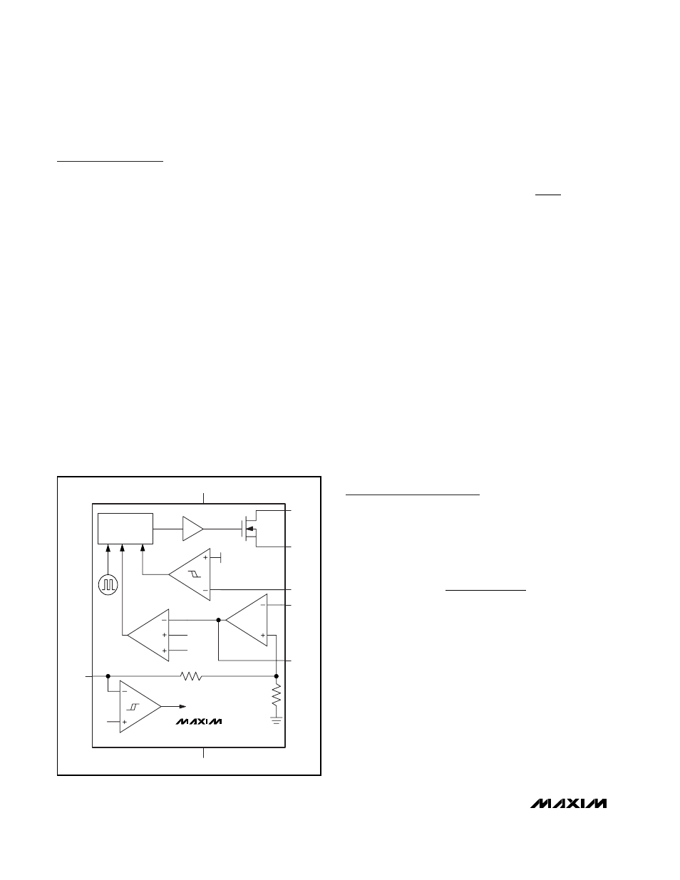
V+
PWM
CONTROL
CURRENT
SENSE
SLOPE
170mV
SHUTDOWN
50k
Ω
617k
Ω
LX
PGND
OUT
CS
COMP
CTRL
GND
1.2MHz
8
13.25V
MAX1848
Figure 1. Functional Diagram