Rainbow Electronics MAX1848 User Manual
General description, Applications, Features
General Description
The MAX1848 drives white LEDs with a constant cur-
rent to provide backlight in cell phones, PDAs, and
other hand-held devices. The step-up converter topology
allows series connection of the white LEDs so that the
LED currents are identical for uniform brightness. This
configuration eliminates the need for ballast resistors
and expensive factory calibration. Other benefits
include greater simplicity, lower cost, higher efficiency,
and greater reliability.
This step-up PWM converter includes an internal, high-
voltage, low R
DSON
N-channel MOSFET switch for high
efficiency and maximum battery life. A single analog
voltage Dual Mode
™
input provides a simple means of
brightness adjustment and on/off control. Fast 1.2MHz
current-mode PWM control allows for small input and
output capacitors and a small inductor while minimizing
ripple on the input supply/battery. Programmable soft-
start eliminates inrush current during startup.
The MAX1848 is available in space-saving 8-pin thin
QFN (3mm
✕
3mm) and 8-pin SOT23 packages.
Applications
Cell Phones and Smart Phones
PDAs, Palmtops, and Wireless Handhelds
e-Books and Subnotebooks
White LED Display Backlighting
Features
♦ Constant Current Regulation for Uniform
Illumination
♦ High 87% Efficiency
♦ Analog or Logic Control of LED Intensity
♦ 0.8W Output Power with Internal High-Voltage
MOSFET Switch
♦ Small, Low-Profile External Components
♦ 2.6V to 5.5V Input Range
♦ 13V Maximum Output with Overvoltage Protection
♦ Optimized for Low Input Ripple
♦ Programmable Soft-Start
♦ 0.3µA Shutdown Current
♦ Small 8-pin Thin QFN (3mm
✕
3mm) and
8-Pin SOT23 Packages
MAX1848
White LED Step-Up Converter in SOT23
________________________________________________________________ Maxim Integrated Products
1
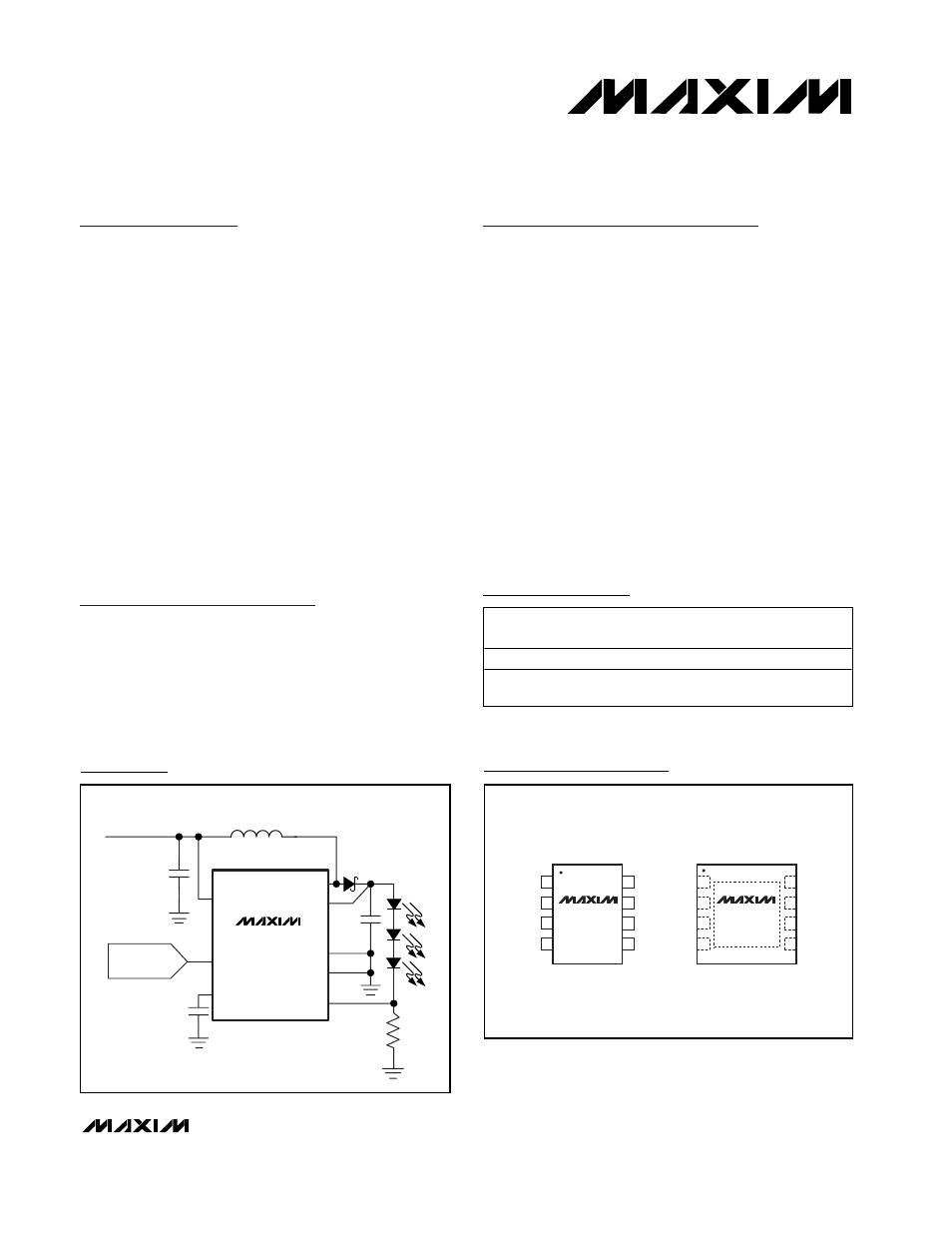
GND
PGND
LX
1
2
8
7
V+
CS
CTRL
OUT
COMP
SOT23
TOP VIEW
3
4
6
5
MAX1848
GND
PGND
LX
1
2
8
7
V+
CS
CTRL
OUT
COMP
THIN QFN
3mm x 3mm
3
4
6
5
MAX1848
Pin Configuration
Ordering Information
V+
CTRL
COMP
LX
OUT
PGND
GND
CS
2.6V to 5.5V
LOGIC
OR DAC
C
IN
3.3
µF
C
COMP
0.15
µF
L1
33
µH
C
OUT
1
µF
R
SENSE
5
Ω
D1
MAX1848
Typical Application Circuit
19-2028; Rev 1; 9/02
PART
TEMP RANGE
PIN-PACKAGE
TOP
MARK
MAX1848EKA
-40
°C to +85°C 8 SOT23
AAIM
MAX1848ETA
-40
°C to +85°C
8 Thin QFN
(3mm
✕
3mm)
ACR
Note: Hand soldering is not recommended for the MAX1848
SOT23 package.
Dual Mode is a trademark of Maxim Integrated Products, Inc.
For pricing, delivery, and ordering information, please contact Maxim/Dallas Direct! at
1-888-629-4642, or visit Maxim’s website at www.maxim-ic.com.