Low-power mode, Input-stage circuitry – Rainbow Electronics MAX977 User Manual
Page 12
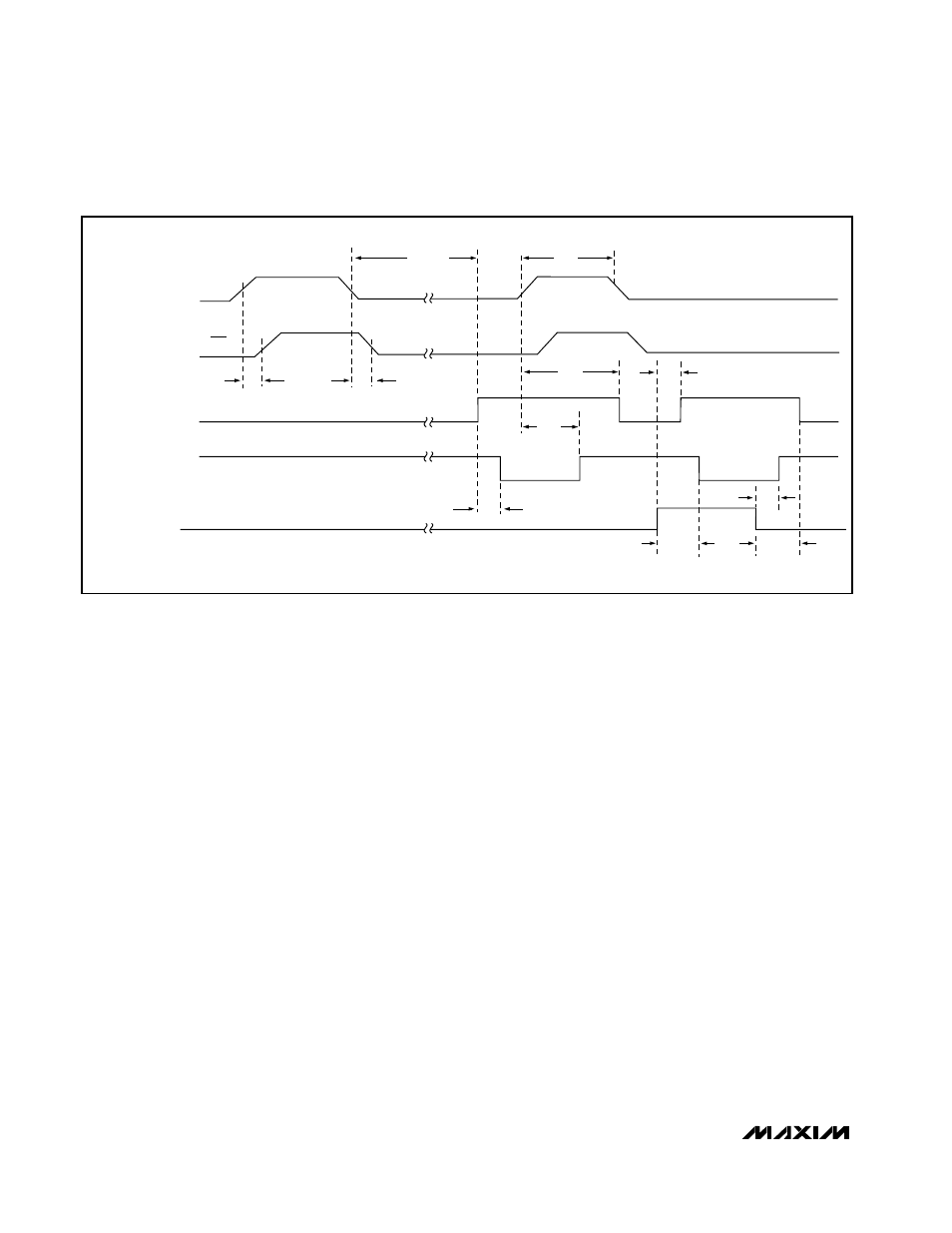
MAX975/MAX977
powered up, the high-speed comparator is enabled,
the low-power comparator is disabled, and STAT goes
high, placing the MAX975 back into high-speed mode
(Figure 2).
Use an external capacitor, C
STO
, to program the timeout
period required for the comparator to enter auto-
standby mode. Determine the capacitor required for a
particular timeout period by the relationship t
ASB
=
10 x Cµs, where C is in pF. For example, connecting a
0.1µF capacitor to STO_ results in a timeout period of
1sec. The propagation delay of OUT_ when exiting auto
standby mode is equivalent to the low - power-mode
propagation delay. When STAT_ goes low, the low-
power comparator is disabled and the high-speed com-
parator is ready for operation. To bring the comparator
out of auto-standby mode without a transition occurring
on OUT_, toggle LP low-high-low. The LP pin is sensitive
to noise. If fall times larger than 10µs are expected,
bypass LP with a 0.1µF capacitor to GND. To disable
auto-standby mode, drive STO_ low or connect it to
ground. Note that driving STO_ low while in auto-
standby mode will not bring the comparator out of auto-
standby mode. Also, if driving STO_ with an open drain,
leakage must be less than 1nA. On power-up, the
device is in high-speed mode unless LP is high. The
MAX977 operates in the same manner as the MAX975.
Low-Power Mode
Driving LP high switches the MAX975/MAX977 to low-
power mode. In this mode, the supply current drops to
a maximum of 5
µ
A, and propagation delay increases
typically to 480ns. The high-speed comparator is dis-
abled and the low-power comparator is enabled for
continuous operation. Return to high-speed mode by
driving LP low. The LP pin is sensitive to noise. If fall
times larger than 10µs are expected, bypass LP with a
0.1µF capacitor to GND. The logic state and sink/
source capabilities of OUT_ remain unchanged in low-
power mode.
Input-Stage Circuitry
The MAX975/MAX977 input common-mode range is
from -0.2V to (V
CC
- 1.2V). But the voltage range for
each comparator input extends to both V
CC
and GND
rails. The output remains in the correct logic state while
one or both of the inputs are within the common-mode
range. If both input levels are out of the common-mode
range, input-stage current saturation occurs and the
output becomes unpredictable.
Single/Dual, +3V/+5V Dual-Speed
Comparators with Auto-Standby
12
______________________________________________________________________________________
t
PWD
t
ASB
t
ASD
t
PD-
t
PD+
t
LPSH
t
ASBE
t
LPCD
t
LPE
t
HSE
V
CC
V
OL
V
OH
V
OS
DIFFERENTIAL
INPUT
VOLTAGE
OUT_
STAT_
I
CC (TYP)
LP
0V
300
µ
A
3
µ
A
t
ASCD
V
CC
A
Figure 2. Timing Diagram