Chip information, Typical application circuit – Rainbow Electronics MAX3738 User Manual
Page 13
Layout Considerations
To minimize loss and crosstalk, keep the connections
between the MAX3738 output and the laser diode as
short as possible. Use good high-frequency layout
techniques and multilayer boards with uninterrupted
ground plane to minimize EMI and crosstalk. Circuit
boards should be made using low-loss dielectrics. Use
controlled-impedance lines for data inputs, as well as
the module output.
Laser Safety and IEC 825
Using the MAX3738 laser driver alone does not ensure
that a transmitter design is IEC 825 compliant. The
entire transmitter circuit and component selections must
be considered. Each customer must determine the level
of fault tolerance required by their application, recogniz-
ing that Maxim products are not designed or authorized
for use as components in systems intended for surgical
implant into the body, for applications intended to sup-
port or sustain life, or for any other application where the
failure of a Maxim product could create a situation
where personal injury or death may occur.
Exposed-Pad (EP) Package
The exposed pad on the 24-pin TQFN provides a very
low thermal resistance path for heat removal from the IC.
The pad is also electrical ground on the MAX3738 and
should be soldered to the circuit board ground for proper
thermal and electrical performance. Refer to Maxim
Application Note HFAN-08.1: Thermal Consideration
for QFN and Other Exposed-Pad Packages at
www.maxim-ic.com for additional information.
Chip Information
TRANSISTOR COUNT: 1884
PROCESSS: SiGe/Bipolar
MAX3738
1Gbps to 2.7Gbps SFF/SFP Laser Driver with
Extinction Ratio Control
______________________________________________________________________________________
13
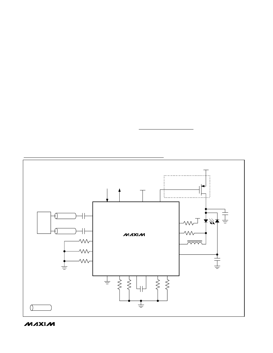
MAX3738
IN+
IN-
REPRESENTS A CONTROLLED-IMPEDANCE TRANSMISSION LINE.
V
CC
SHUTDOWN
+3.3V
OPTIONAL SHUTDOWN
CIRCUITRY
+3.3V
15Ω
10Ω
OUT-
OUT+
BIAS
MD
BC_MON
APCFIL
T1
APCFIL
T2
GND
APCSET
MODSET
TX_DISABLE
TX_F
AUL
T
+3.3V
CDR
C
APC
R
PC_MON
C
MD
0.01µF
FERRITE BEAD
PC_MON
R
BC_MON
R
MODSET
R
APCSET
MODBCOMP
MODTCOMP
TH_TEMP
R
TH_TEMP
R
MODTCOMP
R
MODBCOMP
0.1µF
0.1µF
Typical Application Circuit