Max1195 – Rainbow Electronics MAX1195 User Manual
Page 12
MAX1195
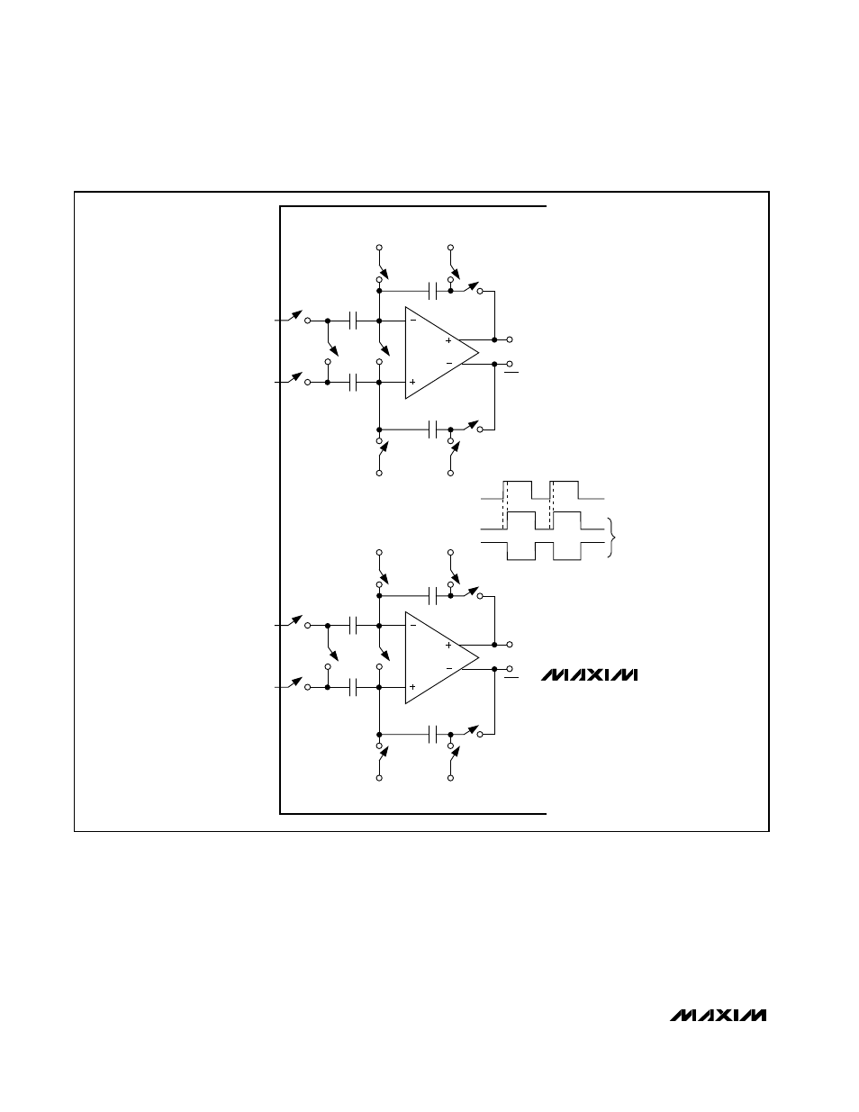
taneously with S1 sampling the input waveform.
Switches S4a, S4b, S5a, and S5b are then opened
before switches S3a and S3b connects capacitors C1a
and C1b to the output of the amplifier and switch S4c is
closed. The resulting differential voltages are held on
capacitors C2a and C2b. The amplifiers are used to
charge capacitors C1a and C1b to the same values
originally held on C2a and C2b. These values are then
presented to the first-stage quantizers and isolate the
pipelines from the fast-changing inputs. The wide input
bandwidth T/H amplifiers allow the MAX1195 to track
and sample/hold analog inputs of high frequencies
(>Nyquist). Both ADC inputs (INA+, INB+ and INA-,
INB-) can be driven either differentially or single-ended.
Match the impedance of INA+ and INA-, as well as
INB+ and INB-, and set the common-mode voltage to
mid-supply (V
DD
/2) for optimum performance.
Dual, 8-Bit, 40Msps, 3V, Low-Power ADC with
Internal Reference and Parallel Outputs
12
______________________________________________________________________________________
S3b
S3a
COM
S5b
S5a
INB+
INB-
S1
OUT
OUT
C2a
C2b
S4c
S4a
S4b
C1b
C1a
INTERNAL
BIAS
INTERNAL
BIAS
COM
HOLD
HOLD
CLK
INTERNAL
NONOVERLAPPING
CLOCK SIGNALS
TRACK
TRACK
S2a
S2b
S3b
S3a
COM
S5b
S5a
INA+
INA-
S1
OUT
OUT
C2a
C2b
S4c
S4a
S4b
C1b
C1a
INTERNAL
BIAS
INTERNAL
BIAS
COM
S2a
S2b
MAX1195
Figure 2. MAX1195 T/H Amplifiers