Table 3. temperature limits vs register settings, 13 registers 54-5bh: fan tachometer low limit, 14 registers 5c-5eh: fan configuration – Rainbow Electronics LM85 User Manual
Page 16: Functional description
Functional Description
(Continued)
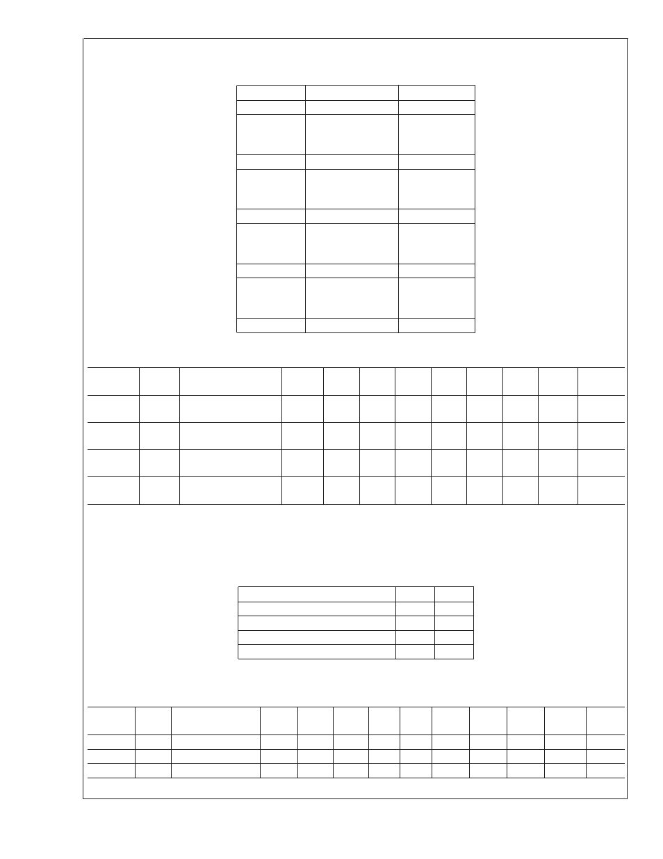
TABLE 3. Temperature Limits vs Register Settings
Temperature
Reading (Decimal)
Reading (Hex)
−127˚C
−127
81h
.
.
.
.
.
.
.
.
.
−50˚C
−50
CEh
.
.
.
.
.
.
.
.
.
0˚C
0
00h
.
.
.
.
.
.
.
.
.
50˚C
50
32h
.
.
.
.
.
.
.
.
.
127˚C
127
7Fh
4.13 Registers 54-5Bh: Fan Tachometer Low Limit
Register
Address
Read/
Write
Register
Name
Bit 7
(MSB)
Bit 6
Bit 5
Bit 4
Bit 3
Bit 2
Bit 1
Bit 0
(LSB)
Default
Value
54h
55h
R/W
R/W
Tach1 Minimum LSB
Tach1 Minimum MSB
7
15
6
14
5
13
4
12
3
11
2
10
1
9
0
8
FFh
FFh
56h
57h
R/W
R/W
Tach2 Minimum LSB
Tach2 Minimum MSB
7
15
6
14
5
13
4
12
3
11
2
10
1
9
0
8
FFh
FFh
58h
59h
R/W
R/W
Tach3 Minimum LSB
Tach3 Minimum MSB
7
15
6
14
5
13
4
12
3
11
2
10
1
9
0
8
FFh
FFh
5Ah
5Bh
R/W
R/W
Tach4 Minimum LSB
Tach4 Minimum MSB
7
15
6
14
5
13
4
12
3
11
2
10
1
9
0
8
FFh
FFh
The Fan Tachometer Low Limit registers indicate the tachometer reading under which the corresponding bit will be set in the
Interrupt Status Register 2 register. In Auto Fan Control mode, the fan can run at low speeds, so care should be taken in software
to ensure that the limit is high enough not to cause sporadic alerts. The fan tachometer will not cause a bit to be set in Interrupt
Status Register 2 if the current value in Current PWM Duty registers is 00h or if the fan 1 disabled via the Fan Configuration
Register. Interrupts will never be generated for a fan if its minimum is set to FF FFh.
Given the insignificance of Bit 0 and Bit 1, these bits could be programmed to remember which fan is which, as follows.
Fan
Bit 1
Bit 0
CPU
0
0
Memory
0
1
Chassis Front
1
0
Chassis Rear
1
1
Setting the Ready/Lock/Start/Override register Lock bit has no effect these registers.
4.14 Registers 5C-5Eh: Fan Configuration
Register
Address
Read/
Write
Register
Name
Bit 7
(MSB)
Bit 6
Bit 5
Bit 4
Bit 3
Bit 2
Bit 1
Bit 0
(LSB)
Default
Value
Lock?
5Ch
R/W
Fan1 Configuration
ZON2
ZON1
ZON0
INV
RES
SPIN2
SPIN1
SPIN0
62h
U
5Dh
R/W
Fan2 Configuration
ZON2
ZON1
ZON0
INV
RES
SPIN2
SPIN1
SPIN0
62h
U
5Eh
R/W
Fan3 Configuration
ZON2
ZON1
ZON0
INV
RES
SPIN2
SPIN1
SPIN0
62h
U
LM85
www.national.com
16