Rainbow Electronics MAX747 User Manual
Page 7
MAX747
High-Efficiency PWM, Step-Down
P-Channel DC-DC Controller
_______________________________________________________________________________________
7
LBI
REF
OUT
CC
FB
AV+
CS
SS
LBO
EXT
V+
LOW-BATTERY
COMPARATOR
ERROR
AMPLIFIER
EXT
CONTROL
CURRENT-SENSE
AMPLIFIER
100mV
SHDN
N
100kHz
OSCILLATOR
+2V
REFERENCE
SOFT-START
CIRCUITRY
Σ
SLOPE
COMPENSATION
RAMP
AGND
50mV
GND
CURRENT-LIMIT
COMPARATOR
PWM
COMPARATOR
IDLE-MODE
COMPARATOR
60k
40k
DUAL-MODE
COMPARATOR
V
RAMP
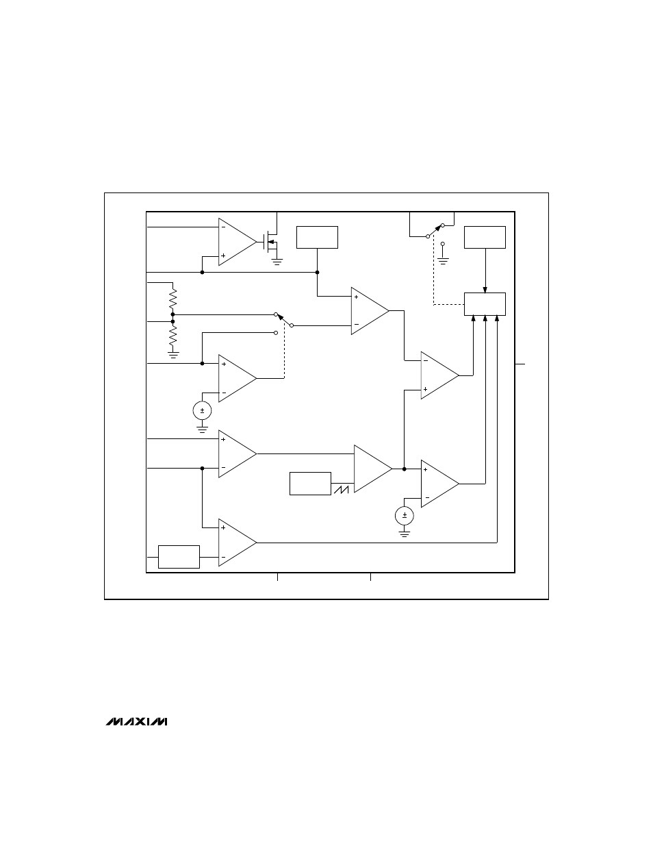
Figure 2. Block Diagram
The Oscillator and EXT Control
The switching frequency is nominally 100kHz and the
duty cycle varies from 5% to 96%, depending on the
input/output voltage ratio. EXT, which provides the gate
drive for the external P-FET, is switched between V+
and GND at the switching frequency. EXT is controlled
by a unique two-comparator control scheme composed
of a PWM comparator and an idle-mode comparator
(Figure 2). The PWM comparator determines the cycle-
by-cycle peak current with heavy loads, and the
light-load comparator sets the light-load peak current.
As V
OUT
begins to drop, EXT goes low and remains low
until both comparators trip. With heavy loads, the idle-
mode comparator trips quickly, and the PWM control
comparator determines the EXT on-time; with light
loads, the idle-mode comparator sets the EXT on-time.