Pin description – Rainbow Electronics MAX768 User Manual
Page 6
MAX768
Low-Noise, Dual-Output, Regulated Charge Pump
for GaAsFET, LCD, and VCO Supplies
6
_______________________________________________________________________________________
9
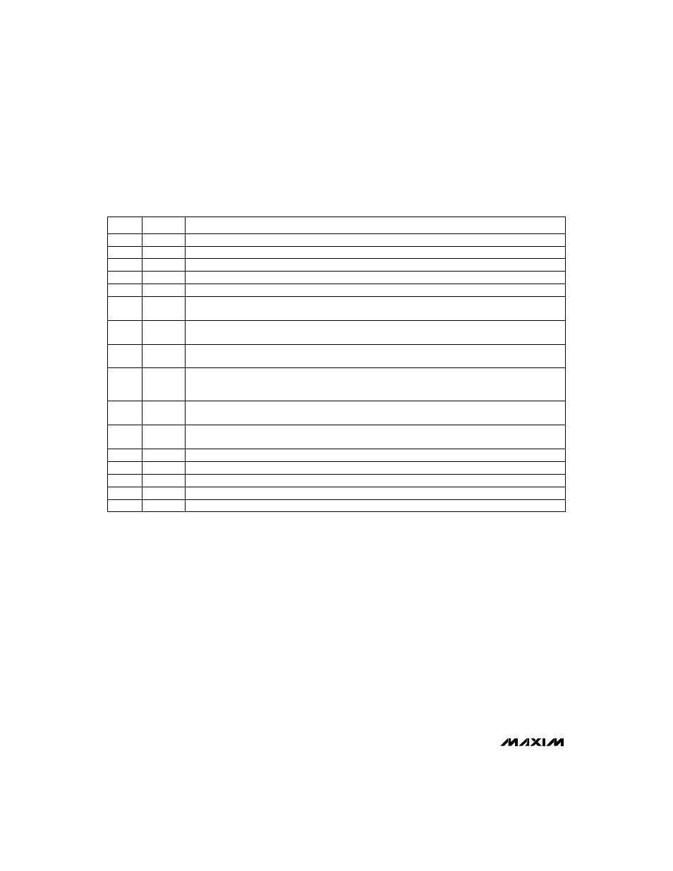
SYNC
Clock Synchronizing Input. Connect an external 20kHz
≤
f
CLK
≤
240kHz to SYNC to synchronize the
MAX768 to that frequency. Connect SYNC to GND to select the internal 25kHz clock, or to IN for the inter-
nal 100kHz clock.
13
V+
Doubler Charge-Pump Output. See Table 2 for capacitor selection.
15
IN
Supply (3V to 5.5V). Bypass IN with 4.7µF to GND.
NAME
FUNCTION
1
C1-
Negative Terminal of the Doubler Charge-Pump Capacitor. See Table 2 for capacitor selection.
16
C2+
Positive Terminal of the Inverter Charge-Pump Capacitor. See Table 2 for capacitor selection.
PIN
14
C1+
Positive Terminal of the Doubler Charge-Pump Capacitor. See Table 2 for capacitor selection.
11
SETP
Set Positive Output Voltage Input. Connect SETP to GND for factory-preset +5V output. Connect a resistor
divider between POUT, SETP, and GND for custom output voltage setting.
12
POUT
Positive Regulator Output. See Table 2 for capacitor selection.
10
RDY
Output-Ready Indicator. This open-drain output pulls to GND when the negative output voltage (NOUT) is
within 10% of the regulation voltage.
5
NOUT
Negative Regulator Output. See Table 2 for capacitor selection.
7
NSHDN
Negative-Supply Shutdown Input. Pull
NSHDN low to turn off the inverting charge pump, the negative reg-
ulator, and the bias-ready indicator. If
PSHDN is also low, the part completely shuts down.
8
PSHDN
Positive-Supply Shutdown Input. Pull
PSHDN low to turn off the positive regulator. If NSHDN is also low,
the part completely shuts down.
6
SETN
Set Negative Output Voltage Input. Connect SETN to GND for factory-preset -5V. Connect a resistor
divider between NOUT, SETN, and GND for custom output voltage setting.
3
C2-
Negative Terminal of the Inverter Charge-Pump Capacitor
4
V-
Inverter Charge-Pump Output. See Table 2 for capacitor selection.
2
GND
Ground
______________________________________________________________Pin Description