Max2036, Ultrasound vga integrated with cw octal mixer – Rainbow Electronics MAX2036 User Manual
Page 18
MAX2036
Synchronization
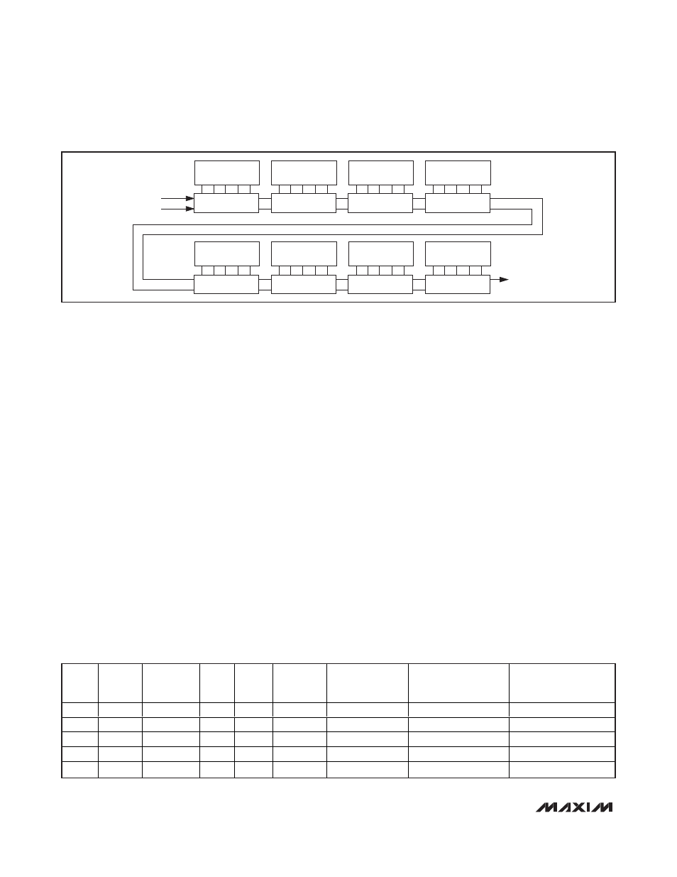
Figure 1 illustrates the serial programming of the 8 indi-
vidual channels through the serial data port. Note that
the serial data can be daisy chained from one part to
another, allowing a single data line to be used to pro-
gram multiple chips in the system.
CW Lowpass Filter
The MAX2036 also includes selectable lowpass filters
between each CW differential input pair and corre-
sponding mixer input. Shunt capacitors and resistors
are integrated on chip for high band and low band. The
parallel capacitor/resistor networks, which appear dif-
ferentially across each of the CW differential inputs, are
selectable through the CW_FILTER. Drive CW_FILTER
high to set the corner frequency of the filter to be f
C
=
9.5MHz. Drive CW_FILTER low to set the corner fre-
quency equal to f
C
= 4.5MHz. The CW_VG allows the
filter inputs to be disconnected from input nodes (inter-
nal to chip) to prevent overloading the LNA output and
to not change the PW input common-mode voltage.
VGA and CW Mixer Operation
During normal operation, the MAX2036 is configured
such that either the VGA path is enabled while the mixer
array is powered down (VGA mode), or the quadrature
mixer array is enabled while the VGA path is powered
down (CW mode). During VGA mode, besides power-
ing down the CW mixer array, the differential inputs to
the lowpass filters and CW mixers also are internally
disconnected from the input nodes, making the CW dif-
ferential inputs (CWIN_+, CWIN_-) high impedance.
The CW mode disconnects the VGA inputs internally
from the input ports of the device. For VGA mode, set
CW_VG to a logic-high, while for CW mode, set CW_VG
to a logic- low.
Power-Down and Low-Power Modes
During device power-down, both the VGA and CW
mixer are disabled regardless of the logic set at
CW_VG. Both the VGA and CW mixer inputs are high
impedance since the internal switches to the inputs are
all disconnected. The total supply current of the device
reduces to 27mA. Set PD to a logic-high for device
power-down.
A low-power mode is available to lower the required
power for CWD operation. When selected, the complex
mixers operate at lower quiescent currents and the total
per-channel current is lowered to 53mA. Note that oper-
ation in this mode slightly reduces the dynamic perfor-
mance of the device. Table 6 shows the logic function
of standard operating modes.
Ultrasound VGA Integrated
with CW Octal Mixer
18
______________________________________________________________________________________
CHANNEL 1
DATA_IN
DATA_OUT
CLOCK
A B
C
D SD
B3 B2 B1 B0 B4
CHANNEL 2
A B
C
D SD
B3 B2 B1 B0 B4
CHANNEL 3
A B
C
D SD
B3 B2 B1 B0 B4
CHANNEL 4
A B
C
D SD
B3 B2 B1 B0 B4
CHANNEL 5
A B
C
D SD
B3 B2 B1 B0 B4
CHANNEL 6
A B
C
D SD
B3 B2 B1 B0 B4
CHANNEL 7
A B
C
D SD
B3 B2 B1 B0 B4
CHANNEL 8
A B
C
D SD
B3 B2 B1 B0 B4
Figure 1. Data Flow of Serial Shift Register
PD
INPUT
CW_VG
INPUT
LOW_PWR
VGA
CW
MIXER
INTERNA
L SWITCH
TO VGA
INTERNAL
SWITCH TO LPF
AND CW MIXER
5V V
CC
CURRENT
CONSUMPTION (mA)
11V V
MIX
CURRENT
CONSUMPTION (mA)
1
1
N/A
Off
Off
Off
Off
27
0
1
0
N/A
Off
Off
Off
Off
27
0
0
0
0
Off
On
Off
On
245
106
0
0
1
Off
On
Off
On
245
53
0
1
N/A
On
Off
On
Off
204
0
Table 6. Logic Function of Standard Operating Modes
N/A = Not applicable.