Electrical characteristics (continued) – Rainbow Electronics MAX1703 User Manual
Page 4
MAX1703
1-Cell to 3-Cell, High-Power (1.5A),
Low-Noise, Step-Up DC-DC Converter
4
_______________________________________________________________________________________
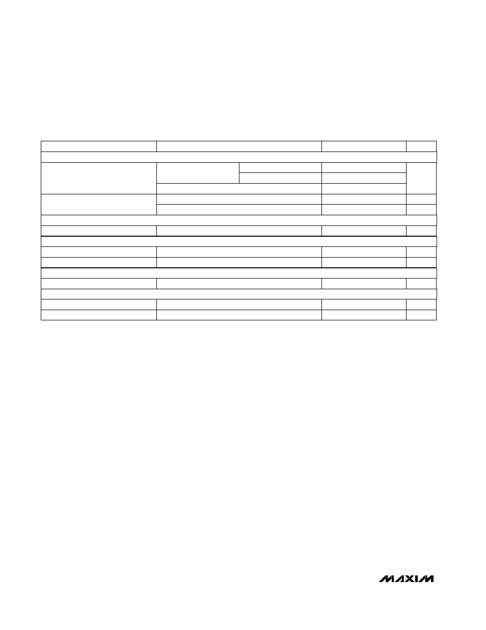
ELECTRICAL CHARACTERISTICS (continued)
(CLK/SEL = AIN = ON = POKIN = FB = PGND = GND, OUT = POUT, LXP = LXN, V
OUT
= 5.3V (Note 1),
T
A
= -40°C to +85°C
, unless
otherwise noted. Typical values are at T
A
= +25°C.) (Note 8)
CLK/SEL = GND
CLK/SEL = OUT
CLK/SEL = GND
CLK/SEL = OUT
N-channel
CONDITIONS
P-channel
Rising V
POKIN
V
1.225
1.275
POKIN Trip Level
0.25
Switch On-Resistance
mA
500
1100
N-Channel Current Limit
mA
2200
3600
0.13
I
AO
= 20µA
Ω
0.25
V
1.23
1.27
AIN Reference Voltage
UNITS
MIN
TYP
MAX
PARAMETER
Note 1:
Supply current from the 5.05V output is measured between the 5.05V output and the OUT pin. This current correlates
directly to the actual battery supply current, but is reduced in value according to the step-up ratio and efficiency. Set
V
OUT
= 5.3V to keep the internal switch open when measuring the device operating current.
Note 2:
Minimum operating voltage. Since the regulator is bootstrapped to the output, once started it will operate down to a 0.7V
input.
Note 3:
Start-up is tested with the circuit of Figure 2.
Note 4:
In low-power mode (CLK/SEL = GND) the output voltage regulates 1% higher than low-noise mode (CLK/SEL = OUT or
synchronized).
Note 5:
The regulator is in start-up mode until this voltage is reached. Do not apply full-load current below this voltage.
Note 6:
Load regulation is measured from no-load to full load, where full load is determined by the N-channel switch current limit.
Note 7:
The ON input has a total hysteresis of approximately 0.15 x V
OUT
.
Note 8:
Specifications to -40°C are guaranteed by design and not production tested.
10µA < I
AO
< 100µA
mmho
5
16
Transconductance
I
REF
= 0µA
V
1.23
1.27
Reference Output Voltage
CLK/SEL = OUT, V
FB
= 0.5V
kHz
260
340
Internal Oscillator Frequency
CLK/SEL = OUT, V
FB
= 0.5V
%
80
92
Oscillator Maximum Duty Cycle
DC-DC SWITCHES
POWER-GOOD COMPARATOR
GAIN BLOCK
REFERENCE
LOGIC INPUTS