Max1703, Design procedure – Rainbow Electronics MAX1703 User Manual
Page 12
MAX1703
__________________Design Procedure
Setting the Output Voltages
Set the output voltage between 2.5V and 5.5V by con-
necting a resistor voltage-divider to FB from OUT to
GND, as shown in Figure 2. The resistor values are then
as follows:
R1 = R2(V
OUT
/ V
FB
- 1)
where V
FB
, the boost-regulator feedback setpoint, is
1.24V. Since the input bias current into FB is less than
20nA, R2 can have a large value (such as 270k
Ω
or
less) without sacrificing accuracy. Connect the resistor
voltage-divider as close to the IC as possible, within
0.2in. (5mm) of the FB pin.
Inductor Selection
The MAX1703’s high switching frequency allows the
use of a small surface-mount inductor. A 4.7µH induc-
tor should have a saturation-current rating that exceeds
the N-channel switch current limit. However, it is gener-
ally acceptable to bias the inductor current into satura-
tion by as much as 20%, although this will slightly
reduce efficiency. For high efficiency, choose an induc-
tor with a high-frequency core material, such as ferrite,
to reduce core losses. To minimize radiated noise, use
a toroid, pot core, or shielded bobbin inductor. See
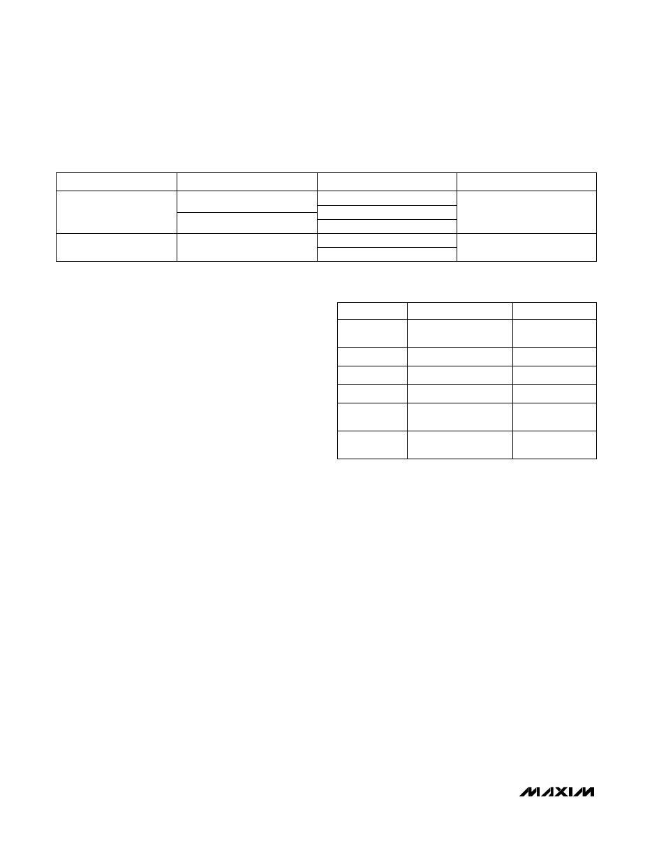
Table 3 for suggested components and Table 4 for a
list of component suppliers. Connect the inductor from
the battery to the LX pins as close to the IC as possible.
Output Diode
Use a Schottky diode such as a 1N5817, MBR0520L, or
equivalent. The Schottky diode carries current during
both start-up and PFM mode after the synchronous recti-
fier turns off. Thus, its current rating only needs to be
500mA. Connect the diode between LXN/LXP and
POUT, as close to the IC as possible. Do not use ordi-
nary rectifier diodes, since slow switching speeds and
long reverse recovery times will compromise efficiency
and load regulation.
Input and Output Filter Capacitors
Choose input and output filter capacitors that will ser-
vice the input and output peak currents with accept-
able voltage ripple. Choose input capacitors with
working voltage ratings over the maximum input volt-
age, and output capacitors with working voltage ratings
higher than the output.
A 330µF, 100m
Ω
, low-ESR tantalum capacitor is recom-
mended for a 5V output. For full output load current,
one 470µF or two 220µF, 100m
Ω
low-ESR tantalum
capacitors are recommended for a 3.3V output. The
input filter capacitor (C
IN
) also reduces peak currents
drawn from the input source and reduces input switch-
ing noise. The input voltage source impedance deter-
mines the required size of the input capacitor.
When operating directly from one or two NiCd cells
placed close to the MAX1703, use a 100µF, low-ESR
input filter capacitor.
Sanyo OS-CON and Panasonic SP/CB-series ceramic
capacitors offer the lowest ESR. Low-ESR tantalum
capacitors are a good choice and generally offer a
good tradeoff between price and performance. Do not
exceed the ripple current ratings of tantalum capaci-
tors. Avoid most aluminum-electrolytic capacitors,
because their ESR is often too high.
1-Cell to 3-Cell, High-Power (1.5A),
Low-Noise, Step-Up DC-DC Converter
12
______________________________________________________________________________________
Sanyo OS-CON series
Sumida RCH654 series
Through Hole
Matsuo 267 series
CAPACITORS
1N5817
DIODES
PRODUCTION
INDUCTORS
Table 3. Component Selection Guide
Table 4. Component Suppliers
(714) 960-6492
USA: (714) 969-2491
Matsuo
(847) 639-1469
USA: (847) 639-6400
Coilcraft
(803) 626-3123
FAX
SUPPLIER
USA: (803) 946-0690
(800) 282-4975
AVX
PHONE
Nichicon PL series
Sprague 595D series
(602) 994-6430
USA: (602) 303-5454
Motorola
(619) 661-1055
81-7-2070-1174
USA: (619) 661-6835
Japan: 81-7-2070-6306
Sanyo
(847) 956-0702
81-3-3607-5144
USA: (847) 956-0666
Japan: 81-3-3607-5111
Sumida
Sumida CDR125
AVX TPS series
Surface Mount
Motorola MBR0520L
Coilcraft DO3316