Ac electrical characteristics – Rainbow Electronics MAX2105 User Manual
Page 2
AGC Input Bias Current
MAX2102/MAX2105
Direct-Conversion Tuner ICs for
Digital DBS Applications
2
_______________________________________________________________________________________
ABSOLUTE MAXIMUM RATINGS
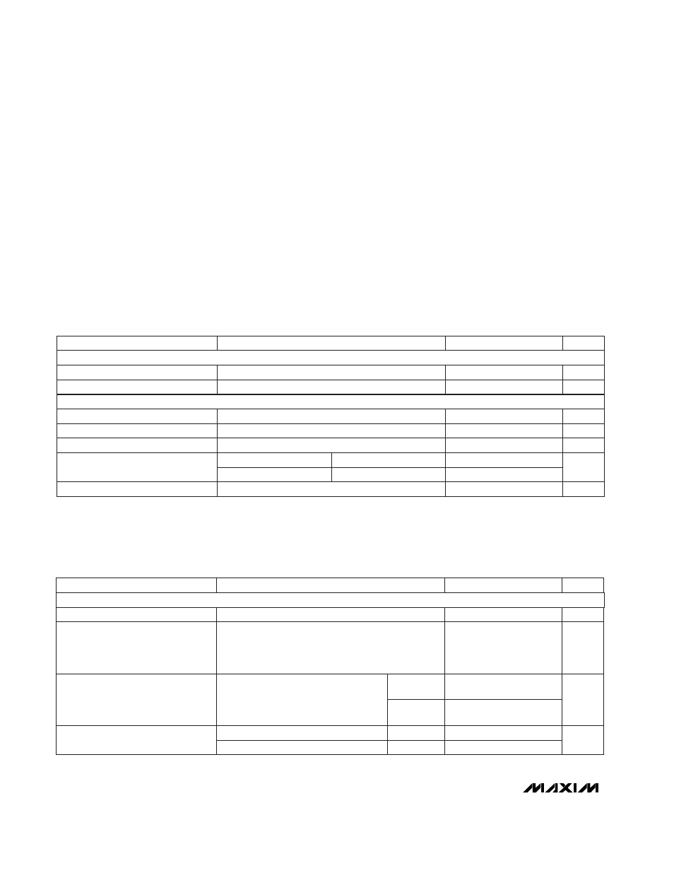
DC ELECTRICAL CHARACTERISTICS
(V
CC
= +4.75V to +5.25V; GND = 0V; PSGND = GND; AGC = 1.3V; MOD = 0.8V; P
RFIN
= OFF, f
LO
= 1450.125MHz; P
LO
= -15dBm;
IOUT, QOUT = open; T
A
= 0°C to +70°C; unless otherwise noted.)
AC ELECTRICAL CHARACTERISTICS
(MAX2102 EV kit circuit (Figure 1); V
CC
= +5V; PSGND = open; MOD = GND; f
RFIN
= 2150MHz; P
RFIN
= -19dBm; f
LO
=
2150.125MHz; P
LO
= -15dBm driven single-ended into LO; AGC set via servo loop for V
IOUT
= V
QOUT
= 0.5Vp-p; IOUT, QOUT drive
AC-coupled 100
Ω
loads; 2k
Ω
from PSOUT to GND; T
A
= +25°C; unless otherwise noted.)
Stresses beyond those listed under “Absolute Maximum Ratings” may cause permanent damage to the device. These are stress ratings only, and functional
operation of the device at these or any other conditions beyond those indicated in the operational sections of the specifications is not implied. Exposure to
absolute maximum rating conditions for extended periods may affect device reliability.
V
CC
to GND ..............................................................-0.5V to +7V
RFIN to
RFIN ..........................................................................±2V
LO to LO ................................................................................±2V
AGC, MOD, RFIN, RFIN, LO, LO to GND .....-0.5V to (V
CC
+ 0.5V)
AGC Current. ....................................................................±30mA
IDC to IDC, QDC to QDC.......................................................±2V
IOUT or QOUT to GND Short-Circuit Duration ...................10sec
PSOUT to GND Short-Circuit Duration.................................None
IDC, IDC, QDC, QDC to GND ....................-0.5V to (V
CC
+ 0.5V)
Continuous Power Dissipation (T
A
= +70°C)
SO (derate 12.5mW/°C above +70°C) ..........................1.025W
Operating Temperature Range...............................0°C to +70°C
Junction Temperature ......................................................+150°C
Storage Temperature Range .............................-65°C to +150°C
Lead Temperature (soldering, 10sec) .............................+300°C
MAX2102
0V
≤
V
MOD
≤
V
CC
CONDITIONS
mA
150
195
Quiescent Supply Current
V
4.75
5.25
Operating Supply Voltage Range
V
2.2
2.6
IOUT, QOUT Common-Mode Voltage
-250
180
V
0.8
MOD Input Low Level
V
2.0
MOD Input High Level
µA
-80
10
MOD Input Bias Current
UNITS
MIN
TYP
MAX
PARAMETER
Refers to single-carrier power generating
V
IOUT
= V
QOUT
= 0.5Vp-p,
950MHz < f
RFIN
< 2150MHz,
950MHz < f
LO
< 2150MHz (Note 2)
(Note 1)
Refers to single-carrier power generating
V
IOUT
= V
QOUT
= 0.5Vp-p,
950MHz < f
RFIN
< 2150MHz,
950MHz < f
LO
< 2150MHz (Note 2)
CONDITIONS
dBm
RFIN Maximum Single-Carrier
Input Power
MHz
950
2150
RFIN Carrier Frequency Range
dBm
-69
RFIN Minimum Single-Carrier
Input Power
50
UNITS
MIN
TYP
MAX
PARAMETER
-19
MAX2102
MAX2105
-60
0.5V
≤
V
AGC
≤
4V
dB
41
AGC Range
MAX2102
MAX2105
RF FRONT END
MAX2105
µA
-180
180
AGC Input Bias Current
SUPPLY
CONTROL INPUTS, PRESCALER
0.5V
≤
V
AGC
≤
4V
1V
≤
V
AGC
≤
4V
1V
≤
V
AGC
≤
4V