Max2022, Detailed description, Pin description – Rainbow Electronics MAX2022 User Manual
Page 9
MAX2022
High-Dynamic-Range, Direct Upconversion
1500MHz to 2500MHz Quadrature Modulator
_______________________________________________________________________________________
9
MAX2022
Detailed Description
The MAX2022 is designed for upconverting differential
in-phase (I) and quadrature (Q) inputs from baseband to
a 1500MHz to 2500MHz RF frequency range.
Applications include single and multicarrier 1800MHz to
2200MHz UMTS/WCDMA, cdma2000, and DCS/PCS
base stations. Direct upconversion architectures are
advantageous since they significantly reduce transmitter
cost, part count, and power consumption as compared
to traditional IF-based double upconversion systems.
The MAX2022 integrates internal baluns, an LO buffer, a
phase splitter, two LO driver amplifiers, two matched
double-balanced passive mixers, and a wideband
quadrature combiner. Precision matching between the
in-phase and quadrature channels, and highly linear
mixers achieves excellent dynamic range, ACLR, 1dB
compression point, and LO and sideband suppression,
making it ideal for four-carrier WCDMA/UMTS operation.
LO Input Balun, LO Buffer, and
Phase Splitter
The MAX2022 requires a single-ended LO input, with a
nominal power of 0dBm. An internal low-loss balun at
the LO input converts the single-ended LO signal to a
differential signal at the LO buffer input. In addition, the
internal balun matches the buffer’s input impedance to
50
Ω over the entire band of operation.
The output of the LO buffer goes through a phase split-
ter, which generates a second LO signal that is shifted
by 90° with respect to the original. The 0° and 90° LO
signals drive the I and Q mixers, respectively.
LO Driver
Following the phase splitter, the 0° and 90° LO signals
are each amplified by a two-stage amplifier to drive the
I and Q mixers. The amplifier boosts the level of the LO
signals to compensate for any changes in LO drive lev-
els. The two-stage LO amplifier allows a wide input
power range for the LO drive. While a nominal LO
power of 0dBm is specified, the MAX2022 can tolerate
LO level swings from -3dBm to +3dBm.
I/Q Modulator
The MAX2022 modulator is composed of a pair of
matched double-balanced passive mixers and a balun.
The I and Q differential baseband inputs accept signals
from DC to beyond 100MHz with differential amplitudes
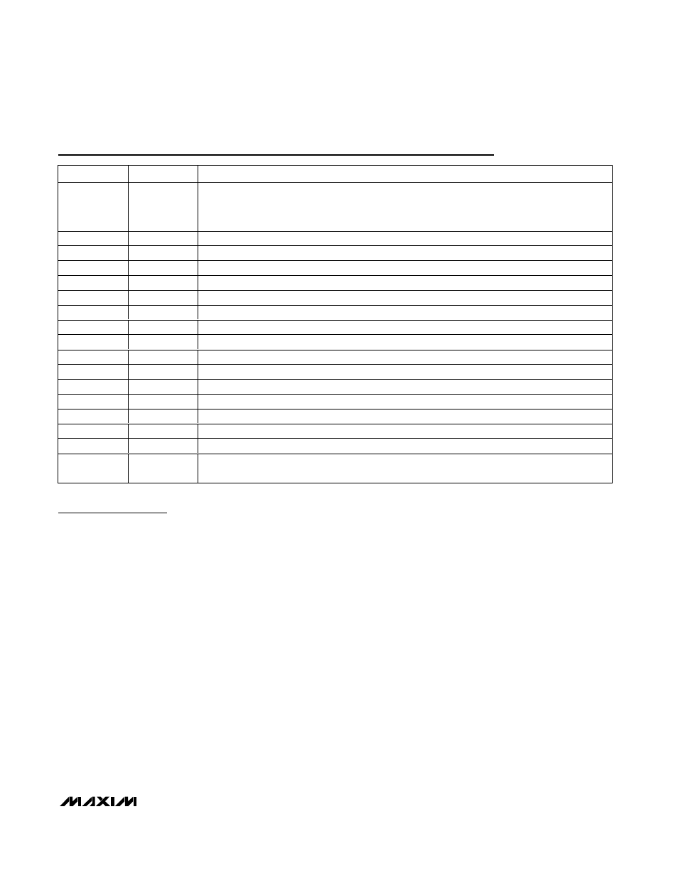
Pin Description
PIN
NAME
FUNCTION
1, 5, 9–12, 14,
16–19, 22, 24,
27–30, 32, 34,
35, 36
GND
Ground
2
RBIASLO3
3rd LO Amplifier Bias. Connect a 301
Ω resistor to ground.
3
VCCLOA
LO Input Buffer Amplifier Supply Voltage
4
LO
Local Oscillator Input. 50
Ω input impedance.
6
RBIASLO1
1st LO Input Buffer Amplifier Bias. Connect a 432
Ω resistor to ground.
7
COMP
Compensation Capacitor Input. Connect a 22pF capacitor to ground.
8
RBIASLO2
2nd LO Amplifier Bias. Connect a 562
Ω resistor to ground.
13
VCCLOI1
I-Channel 1st LO Amplifier Supply Voltage
15
VCCLOI2
I-Channel 2nd LO Amplifier Supply Voltage
20
BBIP
Baseband In-Phase Positive Input
21
BBIN
Baseband In-Phase Negative Input
23
RFOUT
RF Output
25
BBQN
Baseband Quadrature Negative Input
26
BBQP
Baseband Quadrature Positive Input
31
VCCLOQ2
Q-Channel 1st LO Amplifier Supply Voltage
33
VCCLOQ1
Q-Channel 2nd LO Amplifier Supply Voltage
EP
GND
Exposed Ground Paddle. The exposed paddle MUST be soldered to the ground plane using
multiple vias.