Absolute maximum ratings, Dc electrical characteristics, Ac electrical characteristics – Rainbow Electronics MAX2022 User Manual
Page 2
MAX2022
High-Dynamic-Range, Direct Upconversion
1500MHz to 2500MHz Quadrature Modulator
2
_______________________________________________________________________________________
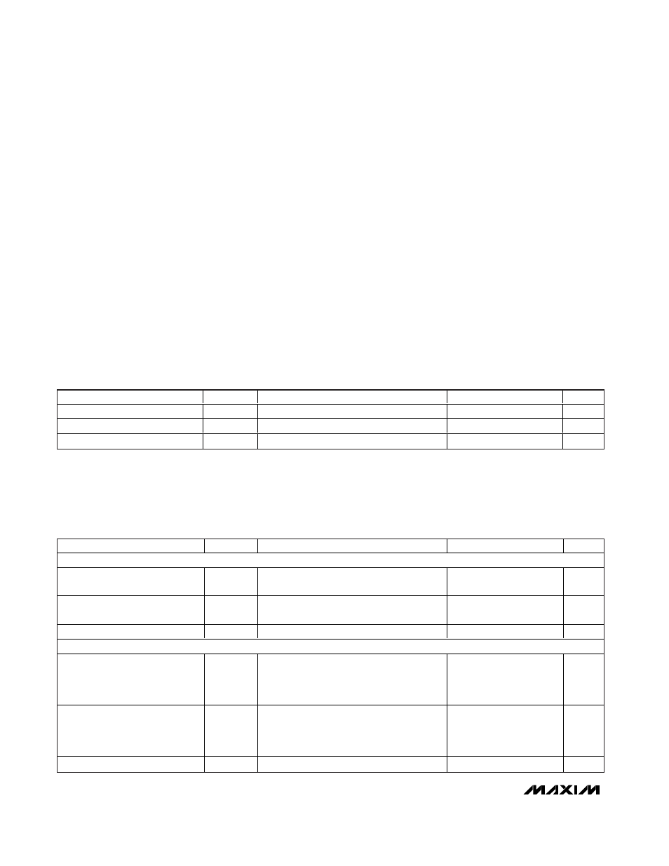
ABSOLUTE MAXIMUM RATINGS
Stresses beyond those listed under “Absolute Maximum Ratings” may cause permanent damage to the device. These are stress ratings only, and functional
operation of the device at these or any other conditions beyond those indicated in the operational sections of the specifications is not implied. Exposure to
absolute maximum rating conditions for extended periods may affect device reliability.
VCC_ to GND ........................................................-0.3V to +5.5V
COMP .............................................................................0 to V
CC
BBIP, BBIN, BBQP, BBQN to GND ............-2.5V to (V
CC
+ 0.3V)
LO, RFOUT to GND Maximum Current ...............................50mA
Baseband Differential I/Q Input Power (Note A) ............+20dBm
LO Input Power...............................................................+10dBm
RBIASLO1 Maximum Current .............................................10mA
RBIASLO2 Maximum Current .............................................10mA
RBIASLO3 Maximum Current .............................................10mA
θ
JA
(without air flow) ..........................................…………34°C/W
θ
JA
(2.5m/s air flow) .........................................................28°C/W
θ
JC
(junction to exposed paddle) ...................................8.5°C/W
Junction Temperature ......................................................+150°C
Storage Temperature Range .............................-65°C to +150°C
Lead Temperature (soldering 10s, non-lead free)...........+245°C
Lead Temperature (soldering 10s, lead free) ..................+260°C
DC ELECTRICAL CHARACTERISTICS
(MAX2022 Typical Application Circuit, V
CC
= +4.75V to +5.25V, GND = 0V, I/Q inputs terminated into 100
Ω differential, LO input ter-
minated into 50
Ω, RF output terminated into 50Ω, R1 = 432Ω, R2 = 562Ω, R3 = 301Ω, T
C
= -40°C to +85°C, unless otherwise noted.
Typical values are at V
CC
= +5V, T
C
= +25°C, unless otherwise noted.) (Note 1)
PARAMETER
SYMBOL
CONDITIONS
MIN
TYP
MAX
UNITS
Supply Voltage
V
CC
4.75
5.00
5.25
V
Total Supply Current
I
TOTAL
Pins 3, 13, 15, 31, 33 all connected to V
CC
292
342
mA
Total Power Dissipation
1460
1796
mW
Note A: Maximum reliable continuous power applied to the baseband differential port is +12dBm from an external 100
Ω source.
AC ELECTRICAL CHARACTERISTICS
(MAX2022 Typical Application Circuit, V
CC
= +4.75V to +5.25V, GND = 0V, I/Q differential inputs driven from a 100
Ω DC-coupled
source, 0V common-mode input, P
LO
= 0dBm, 1900MHz
≤ f
LO
≤ 2200MHz, 50Ω LO and RF system impedance, R1 = 432Ω, R2 =
562
Ω, R3 = 301Ω, T
C
= -40°C to +85°C. Typical values are at V
CC
= +5V, V
BBI
= 109mV
P-P
differential, V
BBQ
= 109mV
P-P
differential,
f
IQ
= 1MHz, T
C
= +25°C, unless otherwise noted.) (Note 1)
PARAMETER
SYMBOL
CONDITIONS
MIN
TYP
MAX
UNITS
BASEBAND INPUT
Baseband Input Differential
Impedance
f
IQ
= 1MHz
43
Ω
BB Common-Mode Input Voltage
Range
-2.5
0
+1.5
V
Output Power
T
C
= +25°C
-24
dBm
RF OUTPUTS (f
LO
= 1960MHz)
Output IP3
V
BBI
, V
BBQ
= 547mV
P-P
differential per tone
into 50
Ω,
f
BB1
= 1.8MHz,
f
BB2
= 1.9MHz
21.8
dBm
Output IP2
V
BBI
, V
BBQ
= 547mV
P-P
differential per tone
into 50
Ω,
f
BB1
= 1.8MHz,
f
BB2
= 1.9MHz
48.9
dBm
Output Power
-20.5
dBm