Pin(note 3), Note 3), Note 4) – Rainbow Electronics LM32 User Manual
Page 6: Note 5), Note 6), Note 7), Note 8), Note 9), Note 11), Note 10)
AC Electrical Characteristics
(Continued)
The following specification apply for V+ = +3.0 V
DC
to +3.6 V
DC
, unless otherwise specified. Boldface limits apply for
T
A
= T
J
= T
MIN
=0˚C to T
MAX
=85˚C; all other limits T
A
= T
J
= 25˚C. The SensorPath Characteristics conform to the SensorPath
specification revision 0.98. Please refer to that speciation for further details.
Symbol
Parameter
Conditions
Typical
Limits
Units
(Limits)
t
RST_MAX
Maximum drive of SWD by an LM32, after the
power supply is raised above 3V
500
ms (max)
Note 1: Absolute Maximum Ratings indicate limits beyond which damage to the device may occur. Operating Ratings indicate conditions for which the device is
functional, but do not guarantee performance limits. For guaranteed specifications and test conditions, see the Electrical Characteristics. The guaranteed
specifications apply only for the test conditions listed. Some performance characteristics may degrade when the device is not operated under the listed test
conditions.
Note 2: All voltages are measured with respect to GND, unless otherwise noted.
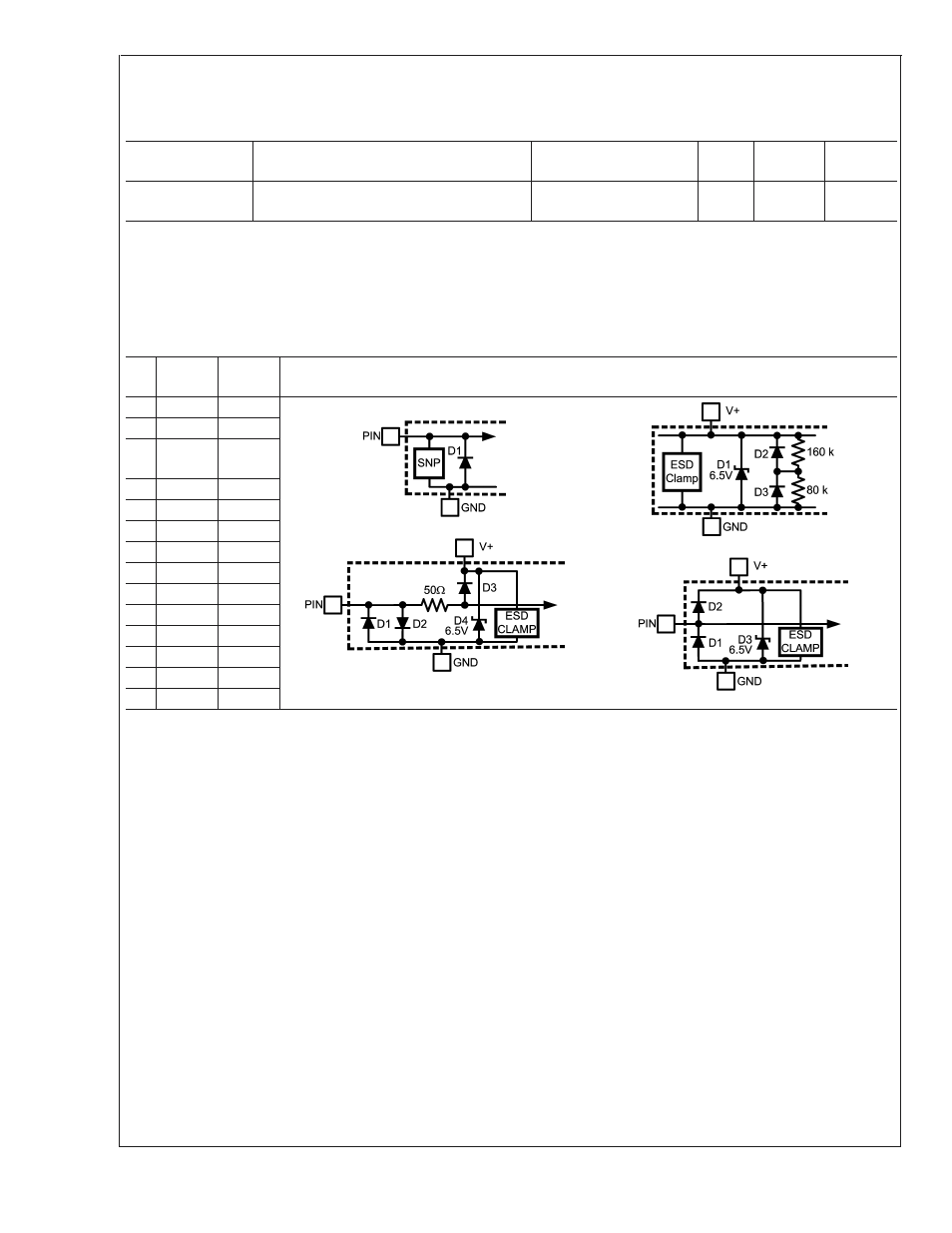
Note 3: When the input voltage (V
IN
) at any pin exceeds the power supplies (V
IN
<
GND or V
IN
>
V+), the current at that pin should be limited to 5 mA. Parasitic
components and/or ESD protection circuitry are shown below for the LM32’s pins. The nominal breakdown voltage of the zener is 6.5 V. SNP stands for snap-back
device.
PIN
#
Pin
Name
Pin
Circuit
All Input Structure Circuits
1
NC
A
Circuit A
Circuit C
Circuit B
Circuit D
2
GND
B
3
V+/
3.3V SB
B
4
SWD
A
5
ADD
A
6
NC
none
7
NC
none
8
D1-
C
9
D1+
D
10
D2-
C
11
D2+
D
12
NC
none
13
NC
none
14
NC
A
Note 4: Thermal resistance junction-to-ambient in still air when attached to a printed circuit board with 1 oz. foil is 148 ˚C/W.
Note 5: Human body model, 100 pF discharged through a 1.5 k
Ω resistor. Machine model, 200 pF discharged directly into each pin.
Note 6: Reflow temperature profiles are different for lead-free and non lead-free packages.
Note 7: “Typicals” are at T
A
= 25˚C and represent most likely parametric norm. They are to be used as general reference values not for critical design calculations.
Note 8: Limits are guaranteed to National’s AOQL (Average Outgoing Quality Level).
Note 9: The supply current will not increase substantially with a SensorPath transaction.
Note 10: Local temperature accuracy does not include the effects of self-heating. The rise in temperature due to self-heating is the product of the internal power
dissipation of the LM32 and the thermal resistance. See (Note 4) for the thermal resistance to be used in the self-heating calculation.
Note 11: The accuracy of the LM32CIMT is guaranteed when using the thermal diode of an Intel 90 nm Pentium 4 processor or any thermal diode with a non-ideality
factor of 1.011 and series resistance of 3.33
Ω. When using a MMBT3904 type transistor as a thermal diode the error band will be typically shifted by -4.5 ˚C.
Note 12: This specification is provided only to indicate how often temperature data are updated.
Note 13: The output fall time is measured from (V
IH min
) to (V
IL max
).
Note 14: The output rise time is measured from (V
IL max
) to (V
IH min
).
Note 15: The rise and fall times are not tested but guaranteed by design.
LM32
www.national.com
6