Connection diagram, Pin description – Rainbow Electronics LM32 User Manual
Page 2
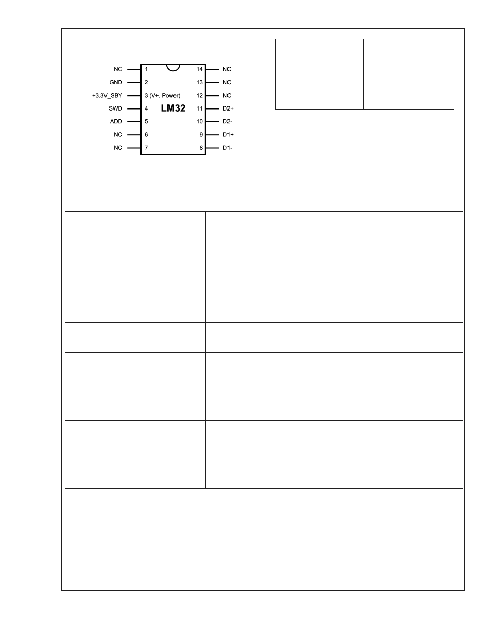
Connection Diagram
TSSOP-14
20071102
Top View
National Package Number MTC14C
Order
Number
Package
Marking
NS
Package
Number
Transport
Media
LM32CIMT
LM32
CIMT
MTC14C
94 units per
rail
LM32CIMTX
LM32
CIMT
MTC14C
2500 units in
tape and reel
Pin Description
Pin Number
Pin Name
Description
Typical Connection
1, 6, 7,12, 13,
14
NC
No Connect
May be tied to V+, GND or left floating
2
GND
Ground
System ground
3
V+/+3.3V_SBY
Positive power supply pin
Connected system 3.3 V standby power and
to a 0.1 µF bypass capacitor in parallel with
100 pF. A bulk capacitance of approximately
10 µF needs to be in the near vicinity of the
LM32.
4
SWD
SensorPath Bus line; Open-drain
output
Super I/O, Pull-up resistor, 1.6k
5
ADD
Digital input - device number select
input for the serial bus device
number
Pull-up to 3.3 V or pull-down to GND resistor,
10k; must never be left floating
8, 10
D1-, D2-
Thermal diode analog voltage
output and negative monitoring
input
Remote Thermal Diode cathode
(THERM_DC) - Diode 1 should always be
connected to the processor thermal diode.
Diode 2 may be connected to an MMBT3904
or GPU thermal diode. A 100 pF capacitor
should be connected between respective D-
and D+ for noise filtering.
9, 11
D1+, D2+
Thermal diode analog current
output and positive monitoring input
Remote Thermal Diode anode (THERM_DA) -
Diode 1 should always be connected to the
processor thermal diode. Diode 2 may be
connected to an MMBT3904 or GPU thermal
diode. A 100 pF capacitor should be
connected between respective D- and D+ for
noise filtering.
LM32
www.national.com
2