Pin description – Rainbow Electronics MAX1621 User Manual
Page 8
MAX1620/MAX1621
Digitally Adjustable LCD Bias Supplies
8
_______________________________________________________________________________________
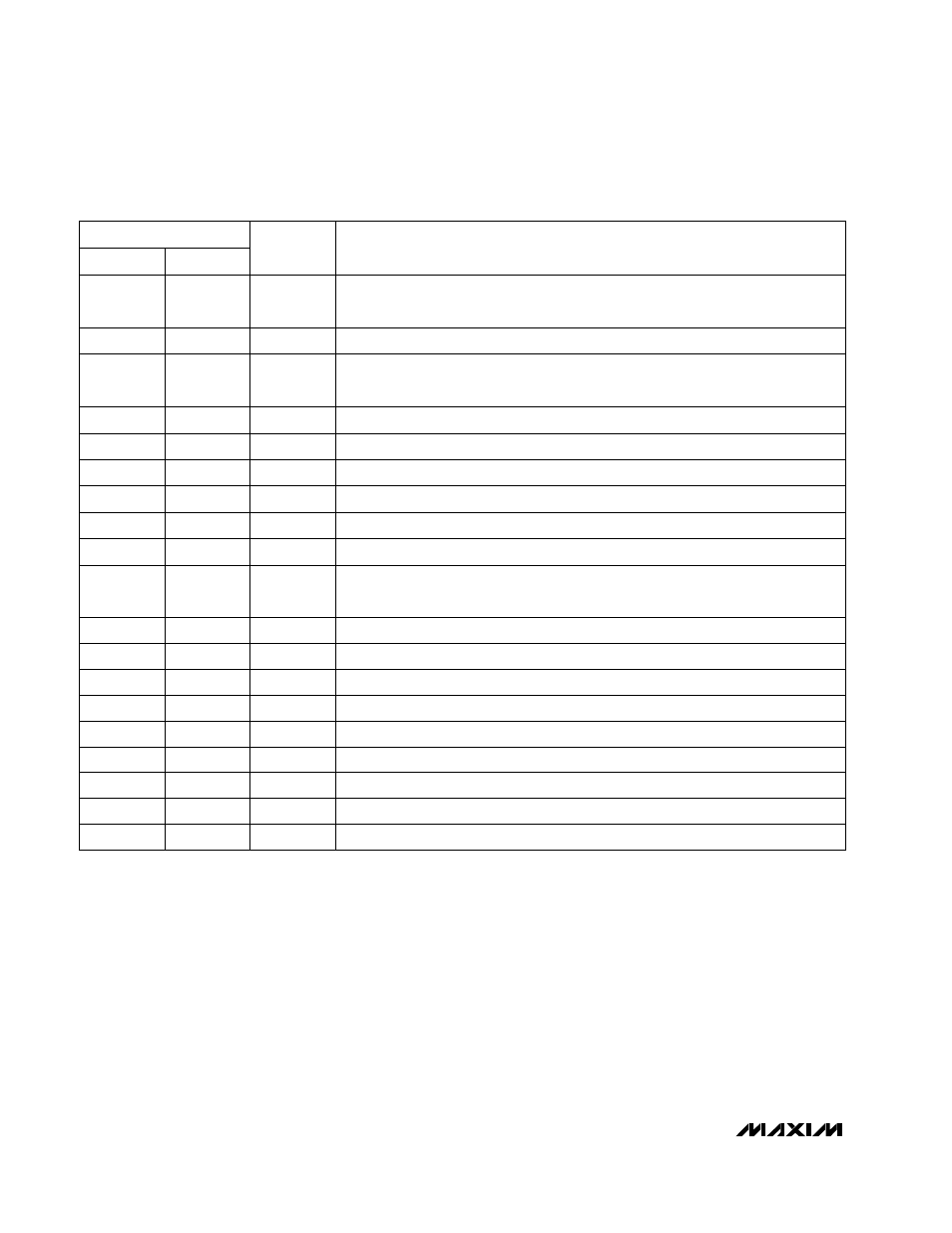
External Transistor Drive, High
DHI
16
16
External Transistor Drive, Low
DLO
15
15
Switching-Voltage Sense Input
LX
14
14
Power Ground
PGND
13
13
Analog Ground
AGND
12
12
IC Input Supply, 3.0V to 5.5V
V
DD
11
11
DAC Output Voltage
Logic-Level Shutdown Input (active-low)
System Management Bus Suspend-Mode Input (active-low)
Power OK Voltage-Sense Input, 1V threshold
Reference Voltage Output. Bypass REF with 0.1µF to AGND.
Logic-Level Input. POL selects output voltage polarity: high = positive boost,
low = negative boost.
Logic-Level Input. A rising edge on UP increases
V
OUT
. UP = DN = high resets
the counter to mid-scale.
DOUT
System Management Bus Serial-Clock Input
Battery Voltage-Sense Input
System Management Bus Serial-Data Input and Open-Drain Output
10
Logic-Level Input. A rising edge on DN decreases
V
OUT
. UP = DN = high resets
the counter to mid-scale.
10
FUNCTION
SHDN
—
4
SUS
4
—
POK
5
5
REF
6
6
POL
7
7
UP
—
2
Feedback Voltage Input
FB
9
SCL
2
—
BATT
3
3
SDA
1
—
9
Open-Drain Output. LCDON controls LCD with external PNP.
LCDON
8
DN
—
1
8
MAX1621
MAX1620
NAME
PIN
______________________________________________________________Pin Description