Ac electrical characteristics – Rainbow Electronics MAX2690 User Manual
Page 2
MAX2690
Low-Noise, 2.5GHz
Downconverter Mixer
2
_______________________________________________________________________________________
ABSOLUTE MAXIMUM RATINGS
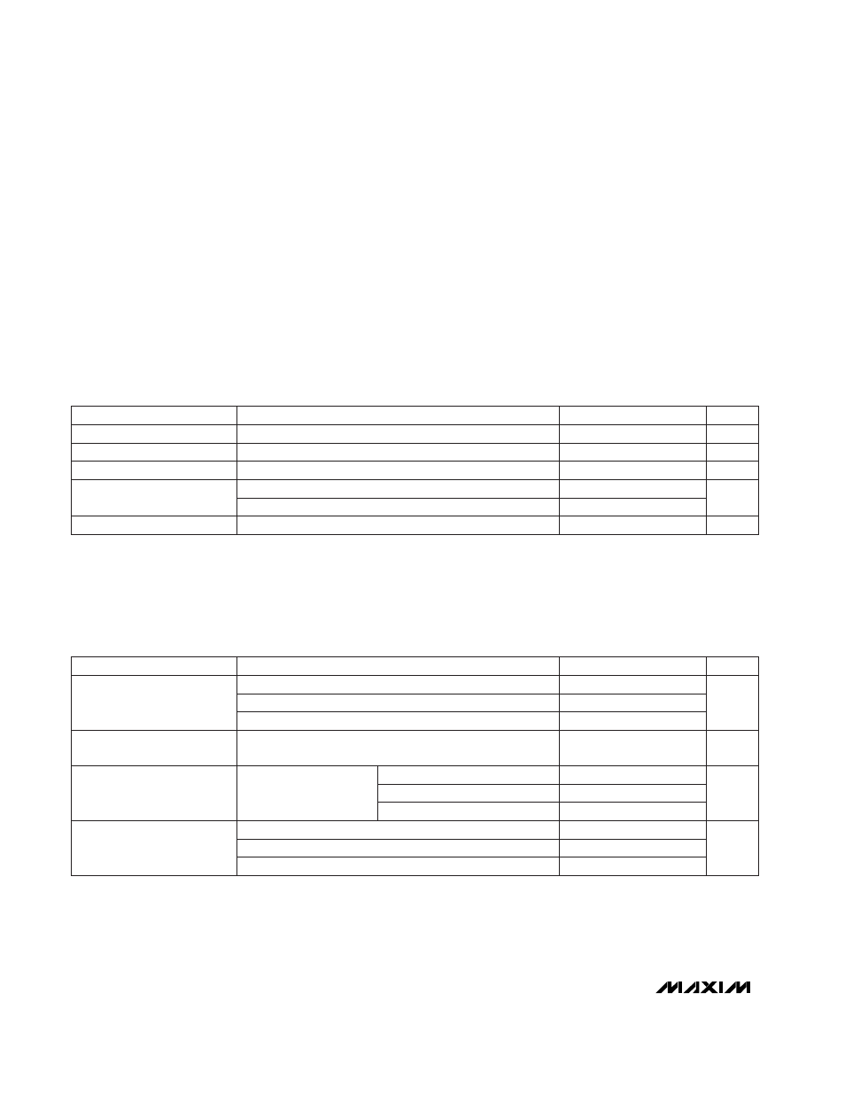
DC ELECTRICAL CHARACTERISTICS
(V
CC
= +2.7V to +5.5V, no RF signals applied, LO = open, IFOUT+ = IFOUT- = V
CC
,
SHDN = high, LGND = GND = GNDLO = 0V,
T
A
= T
MIN
to T
MAX
. Typical values are at V
CC
= +3.0V and T
A
= +25°C, unless otherwise noted. Minimum and maximum values are
guaranteed by design and characterization over temperature.)
AC ELECTRICAL CHARACTERISTICS
(MAX2690 EV kit; V
CC
= +3.0V; P
LO
= -3dBm; P
RF
= -25dBm; SHDN = high; RFIN matched for 900MHz, 1.95GHz, and 2.45GHz as
noted below. Inductor connected from LGND to GND = 39nH for 900MHz operation, 27nH for 1.95GHz operation, and 6.8nH for
2.45GHz operation. T
A
= +25°C, unless otherwise noted.)
Stresses beyond those listed under “Absolute Maximum Ratings” may cause permanent damage to the device. These are stress ratings only, and functional
operation of the device at these or any other conditions beyond those indicated in the operational sections of the specifications is not implied. Exposure to
absolute maximum rating conditions for extended periods may affect device reliability.
V
CC
to GND ...........................................................-0.3V to +6.0V
RFIN Input Power..............................................................10dBm
LO Input Power .................................................................10dBm
SHDN Input Voltage ...................................-0.3V to (V
CC
+ 0.3V)
Continuous Power Dissipation
10-Pin µMAX (derate 4.1mW/°C above +70°C) ............330mW
Operating Temperature Range
MAX2690EUB ...................................................-40°C to +85°C
Junction Temperature ......................................................+150°C
Storage Temperature Range .............................-65°C to +165°C
Lead Temperature (soldering, 10sec) .............................+300°C
SHDN = 0V
SHDN = low
0V < SHDN < V
CC
CONDITIONS
V
0.5
Shutdown Input Voltage Low
V
2
mA
9.5
16
20.1
Operating Supply Current
Shutdown Input Voltage High
0.4
µA
2
Shutdown Supply Current
µA
-5
4
25
Shutdown Input Bias Current
UNITS
MIN
TYP
MAX
PARAMETER
f
RF
= 2.45GHz, f
LO
= 2.1GHz
f
RF
= 1.95GHz, f
LO
= 1.75GHz
f
RF
= 900MHz, f
LO
= 1.1GHz
f
RF
= 1.95GHz, T
A
= T
MIN
to T
MAX
(Note 2)
CONDITIONS
dB
4
6.4
7.9
Conversion Gain
(Note 1)
dB
±0.6
±1.2
Gain Variation over
Temperature
UNITS
MIN
TYP
MAX
PARAMETER
Two tones at
-25dBm per tone,
f
RF2
= 1MHz above f
RF
f
RF
= 900MHz, f
LO
= 1.1GHz
dBm
4.3
5.3
7.6
Input Third-Order Intercept
10
f
RF
= 2.45GHz, f
LO
= 2.1GHz
f
RF
= 1.95GHz, f
LO
= 1.75GHz
dB
12
Noise-Figure
Single Sideband
11.5
f
RF
= 900MHz, f
LO
= 1.1GHz
f
RF
= 1.95GHz, f
LO
= 1.75GHz
f
RF
= 2.45GHz, f
LO
= 2.1GHz