Applications information – Rainbow Electronics MAX1081 User Manual
Page 15
MAX1080/MAX1081
300ksps/400ksps, Single-Supply, Low-Power,
8-Channel, Serial 10-Bit ADCs with Internal Reference
______________________________________________________________________________________
15
___________Applications Information
Power-On Reset
When power is first applied, and if SHDN is not pulled
low, internal power-on reset circuitry activates the
MAX1080/MAX1081 in normal operating mode, ready to
convert with SSTRB = low. The MAX1080/MAX1081
require 10µs to reset after the power supplies stabilize;
no conversions should be initiated during this time. If
CS is low, the first logical 1 on DIN is interpreted as a
start bit. Until a conversion takes place, DOUT shifts out
zeros. Additionally, wait for the reference to stabilize
when using the internal reference.
Power Modes
You can save power by placing the converter in one of
two low-current operating modes or in full power-down
between conversions. Select the power mode through
bit 1 and bit 0 of the DIN control byte (Tables 3 and 4),
or force the converter into hardware shutdown by dri-
ving SHDN to GND.
The software power-down modes take effect after the
conversion is completed; SHDN overrides any software
power mode and immediately stops any conversion in
progress. In software power-down mode, the serial
interface remains active while waiting for a new control
byte to start conversion and switch to full-power mode.
Once the conversion is completed, the device goes into
the programmed power mode until a new control byte
is written.
The power-up delay is dependent on the power-down
state. Software low-power modes will be able to start
conversion immediately when running at decreased
clock rates (see Power-Down Sequencing). During
power-on reset, when exiting software full power-down
mode, or when exiting hardware shutdown, the device
goes immediately into full-power mode and is ready to
convert after 2µs when using an external reference.
When using the internal reference, wait for the typical
power-up delay from a full power-down (software or
hardware) as shown in Figure 9.
Software Power-Down
Software power-down is activated using bits PD1 and
PD0 of the control byte. When software power-down is
asserted, the ADC completes the conversion in
progress and powers down into the specified low-qui-
escent-current state (2µA, 0.9mA, or 1.3mA).
The first logic 1 on DIN is interpreted as a start bit and
puts the MAX1080/MAX1081 into its full-power mode.
Following the start bit, the data input word or control
byte also determines the next power-down state. For
example, if the DIN word contains PD1 = 0 and PD0 = 1,
a 0.9mA power-down resumes after one conversion.
Table 4 details the four power modes with the corre-
sponding supply current and operating sections. For
data rates achievable in software power-down modes,
see Power-Down Sequencing.
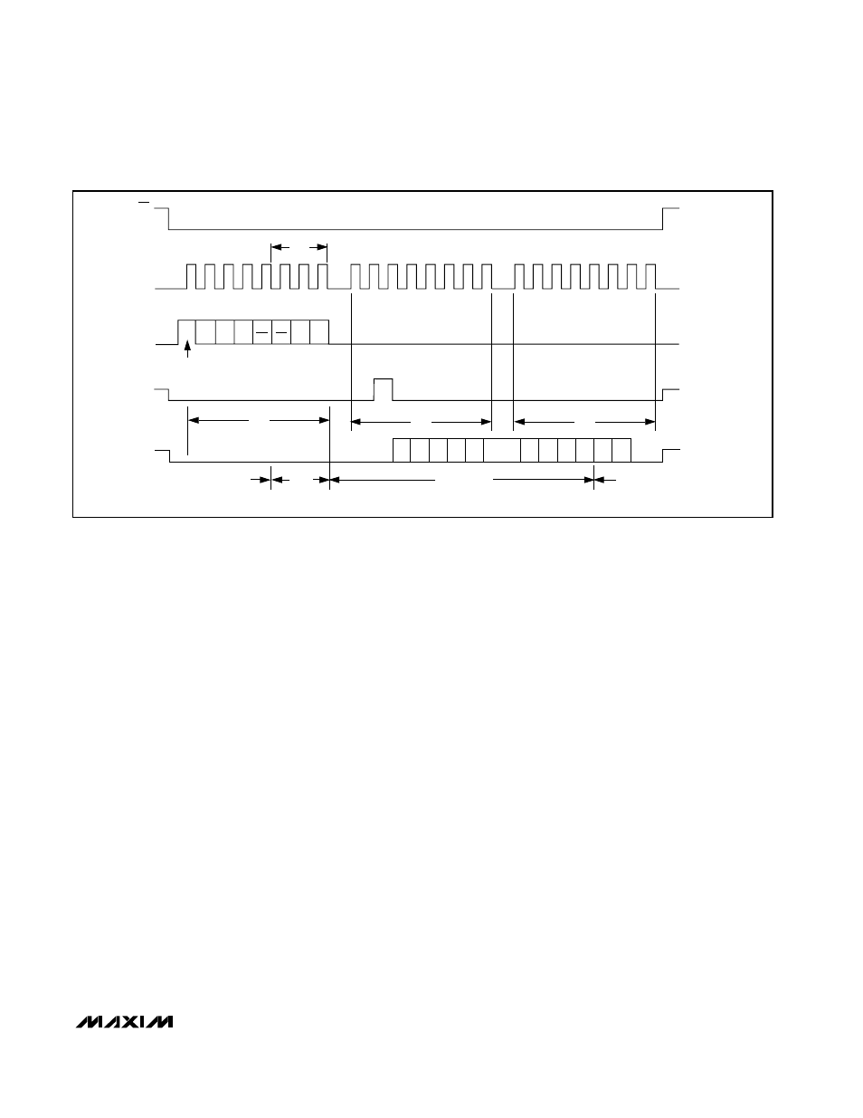
ACQUISITION
IDLE
CS
SCLK
DIN
SSTRB
DOUT
t
ACQ
IDLE
CONVERSION
RB3
RB2
RB1
SEL
2
1
START
4
8
9
12
16
20
24
SEL
1
SEL
0
UNI/
BIP
SGL/
DIF PD1 PD0
B9 B8
B7
B6 B5
B4
B3
B2
B1 B0
S1
S0
HIGH-Z
HIGH-Z
HIGH-Z
HIGH-Z
Figure 6. Single-Conversion Timing