Typical operating characteristics (continued), Pin description – Rainbow Electronics DS3903 User Manual
Page 6
DS3903
Triple 128-Position Nonvolatile
Digital Potentiometer
6
______________________________________________________________________
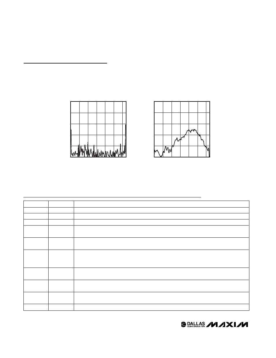
Typical Operating Characteristics (continued)
(VCC = 5.0V, 10k
Ω plots apply to both pot0 and pot2, TA = +25°C unless otherwise noted.)
VOLTAGE-DIVIDER ABSOLUTE LINEARITY
vs. WIPER SETTING (90k
Ω
)
DS3903 toc13
WIPER SETTING
ABSOLUTE LINEARTIY (LSB)
100
80
60
40
20
0.04
0.08
0.12
0.16
0.20
0
0
120
VOLTAGE-DIVIDER RELATIVE LINEARITY
vs. WIPER SETTING (90k
Ω
)
DS3903 toc12
WIPER SETTING
RELATIVE LINEARTIY (LSB)
100
80
60
40
20
0.01
0.02
0.03
0.04
0.05
0
0
120
Pin Description
PIN
NAME
FUNCTION
1
SDA
2-Wire Serial Data. Input/output for 2-wire data.
2
SCL
2-Wire Serial Clock. Input for 2-wire clock.
3
A0
Address-Select Input. Determines device 2-wire address.
4
WP
Write-Protect Input. Must be grounded to write to the potentiometer registers. An internal pullup locks
the potentiometer positions if this pin is not connected.
5, 16, 17
18, 19
N.C.
No Connection
6, 8, 9
L0, L1, L2
Potentiometer Low Terminals. Voltages on these pins should remain between GND and +5.5V while
V
CC
is above +2.7V. Low terminals can be at potentials above the wiper or high terminals.
7, 12, 14
W1, W2, W0
Potentiometer Wiper Terminal. Voltages on these pins should remain between GND and +5.5V while
V
CC
is above +2.7V.
10
GND
Ground Terminal
11, 13, 15
H2, H1, H0
Potentiometer High Terminals. Voltages on these pins should remain between GND and +5.5V while
V
CC
is above +2.7V. High terminals can be at potentials below the low terminals.
20
V
CC
Supply Voltage Terminal