Wire signaling, Initialization timing figure 13, Read/write time slots – Rainbow Electronics DS18B20 User Manual
Page 14: Write time slots
DS18B20
14 of 20
1-WIRE SIGNALING
The DS18B20 uses a strict 1-wire communication protocol to insure data integrity. Several signal types
are defined by this protocol: reset pulse, presence pulse, write 0, write 1, read 0, and read 1. All of these
signals, with the exception of the presence pulse, are initiated by the bus master.
INITIALIZATION PROCEDURE: RESET AND PRESENCE PULSES
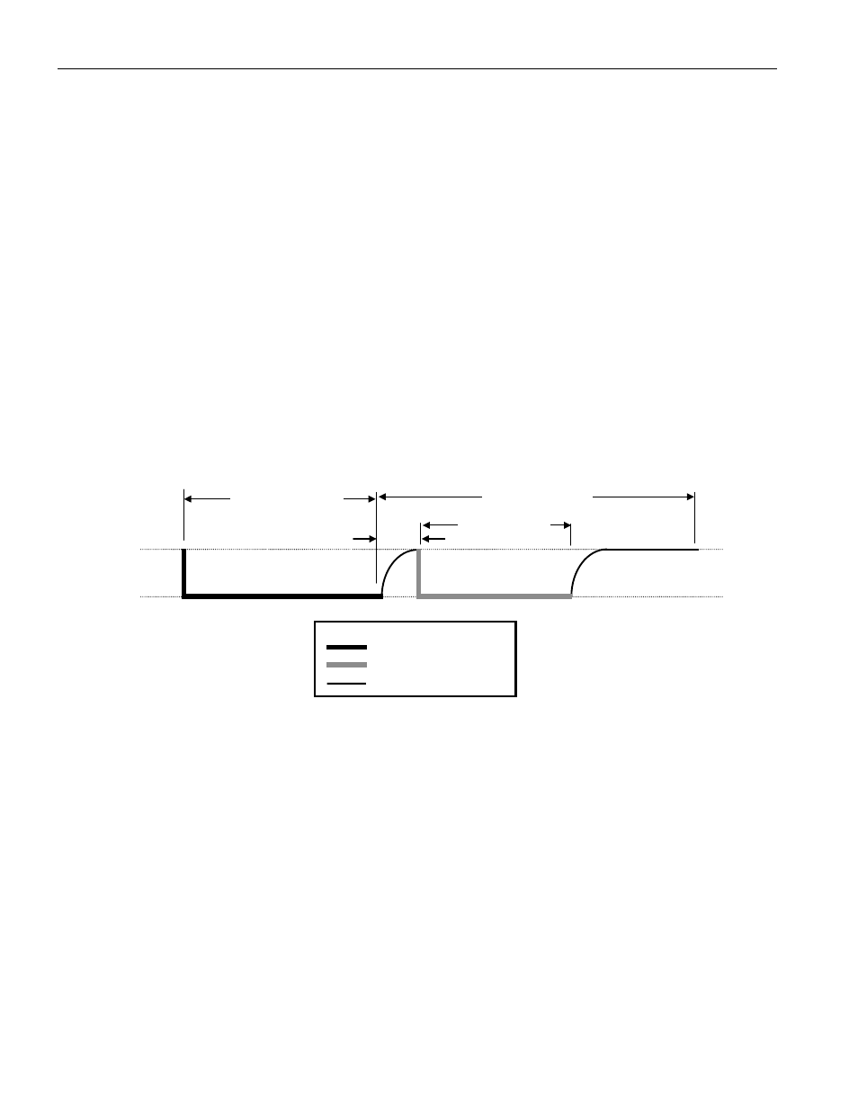
All communication with the DS18B20 begins with an initialization sequence that consists of a reset pulse
from the master followed by a presence pulse from the DS18B20. This is illustrated in Figure 13. When
the DS18B20 sends the presence pulse in response to the reset, it is indicating to the master that it is on
the bus and ready to operate.
During the initialization sequence the bus master transmits (T
X
) the reset pulse by pulling the 1-wire bus
low for a minimum of 480
µ
s. The bus master then releases the bus and goes into receive mode (R
X
).
When the bus is released, the 5k pullup resistor pulls the 1-wire bus high. When the DS18B20 detects
this rising edge, it waits 15–60
µ
s and then transmits a presence pulse by pulling the 1-wire bus low for
60–240
µ
s.
INITIALIZATION TIMING Figure 13
READ/WRITE TIME SLOTS
The bus master writes data to the DS18B20 during write time slots and reads data from the DS18B20
during read time slots. One bit of data is transmitted over the 1-wire bus per time slot.
WRITE TIME SLOTS
There are two types of write time slots: “Write 1” time slots and “Write 0” time slots. The bus master
uses a Write 1 time slot to write a logic 1 to the DS18B20 and a Write 0 time slot to write a logic 0 to the
DS18B20. All write time slots must be a minimum of 60
µ
s in duration with a minimum of a 1
µ
s
recovery time between individual write slots. Both types of write time slots are initiated by the master
pulling the 1-wire bus low (see Figure 14).
To generate a Write 1 time slot, after pulling the 1-wire bus low, the bus master must release the 1-wire
bus within 15
µ
s. When the bus is released, the 5k pullup resistor will pull the bus high. To generate a
Write 0 time slot, after pulling the 1-wire bus low, the bus master must continue to hold the bus low for
the duration of the time slot (at least 60
µ
s).
LINE TYPE LEGEND
Bus master pulling low
DS18B20 pulling low
Resistor pullup
V
PU
GND
1-WIRE BUS
480
µµµµ
s minimum
480
µµµµ
s minimum
DS18B20 T
X
presence pulse
60-240
µµµµ
s
MASTER T
X
RESET PULSE
MASTER R
X
DS18B20
waits 15-60
µµµµ
s