Rainbow Electronics DS2505 User Manual
Page 4
DS2505
4 of 24
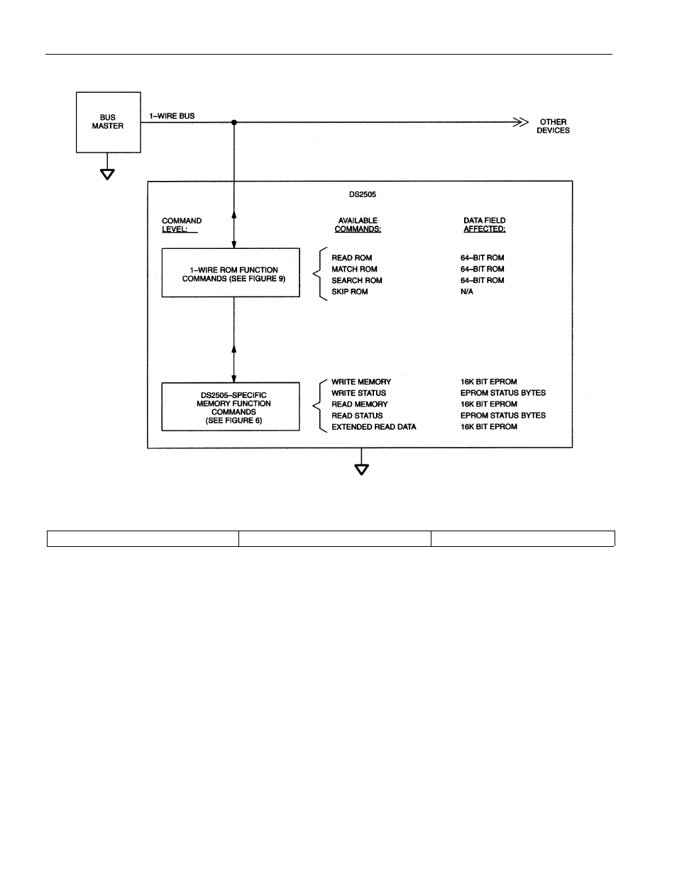
HIERARCHICAL STRUCTURE FOR 1-WIRE PROTOCOL Figure 2
64-BIT LASERED ROM Figure 3
8-Bit CRC Code
48-Bit Serial Number
8-Bit Family Code (0BH)
MSB
LSB MSB
LSB MSB
LSB
16384-BITS EPROM
The memory map in Figure 4 shows the 16384-bit EPROM section of the DS2505 which is configured as
64 pages of 32 bytes each. The 8-bit scratchpad is an additional register that acts as a buffer when
programming the memory. Data is first written to the scratchpad and then verified by reading a 16-bit
CRC from the DS2505 that confirms proper receipt of the data and address. If the buffer contents are
correct, a programming voltage should be applied and the byte of data will be written into the selected
address in memory. This process ensures data integrity when programming the memory. The details for
reading and programming the 16384-bit EPROM portion of the DS2505 are given in the Memory
Function Commands section.
- MAX16840 (1 page)
- MAX9258 (54 pages)
- MAX66140 (21 pages)
- MAX9393 (14 pages)
- MAX66040 (25 pages)
- MAX6981 (1 page)
- MAX6965 (23 pages)
- MAX66100 (16 pages)
- MAX9135 (19 pages)
- MAX66020 (25 pages)
- MAX17127 (22 pages)
- MAX13175E (38 pages)
- MAX16820 (10 pages)
- MAX13237E (16 pages)
- MAX13483E (19 pages)
- MAX13362 (14 pages)
- MAX13486E (16 pages)
- MAX7311 (17 pages)
- MAX8759 (31 pages)
- SCAN92LV090 (13 pages)
- MAX6973 (23 pages)
- MAX13047E (14 pages)
- MAX16831 (20 pages)
- MAX14770E (15 pages)
- MAX11835 (1 page)
- MAX9621 (14 pages)
- MAX9217 (16 pages)
- MAX16841 (18 pages)
- MAX16834 (22 pages)
- MAX7315 (27 pages)
- MAX8645Y (15 pages)
- MAX6975 (23 pages)
- MAX6971 (12 pages)
- MAX3028 (21 pages)
- MAX9395 (13 pages)
- MAX7313 (27 pages)
- MAX6970 (1 page)
- MAX4821 (13 pages)
- MAX4895E (8 pages)
- MAX16823 (13 pages)
- MAX6963 (34 pages)
- MAX9216 (17 pages)
- MAX66000 (21 pages)
- MAX66120 (24 pages)
- MAX13223E (11 pages)