Ds4303 voltage sample and infinite hold – Rainbow Electronics DS4303 User Manual
Page 7
DS4303
Voltage Sample and Infinite Hold
_____________________________________________________________________
7
During the V
OUT
self-adjust period, the DS4303 inter-
nally adjusts the onboard DAC until V
OUT
matches V
IN
.
After V
OUT
has stabilized to within the tracking accura-
cy, V
OUTTA
, of V
IN
, it will be automatically stored in
EEPROM. The storage period lasts for the duration of
the EEPROM write time, t
W
. After the first adjustment
procedure has completed, V
OUT
can be measured,
and if necessary V
IN
can be readjusted and the entire
adjustment procedure can be repeated to fine-tune
V
OUT
within the V
OUTQ
range.
Following each self-adjust procedure, V
OUT
is saved
indefinitely, even if the DS4303 is power cycled.
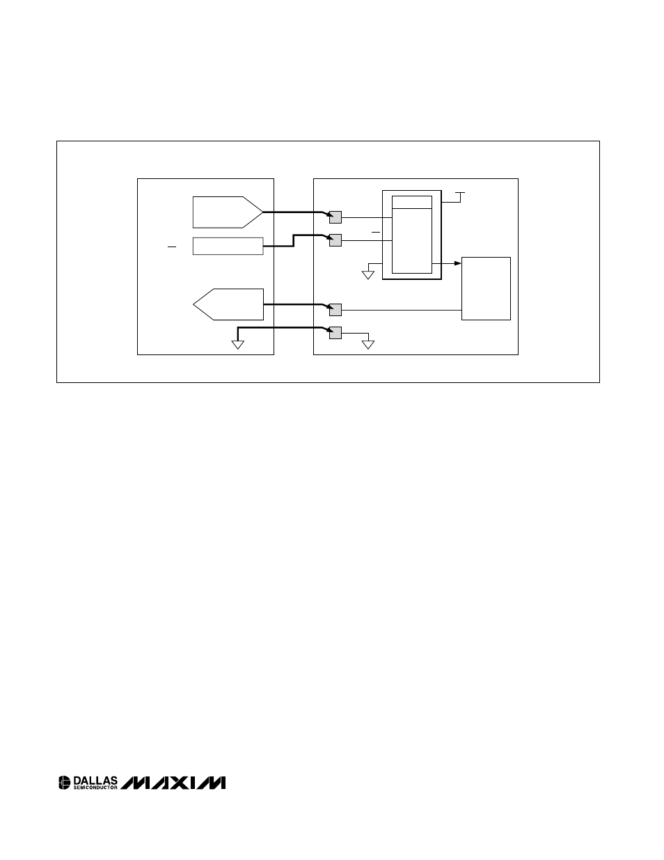
Automated Programming Procedure
Figure 2 details an example of how the DS4303 can be
adjusted in an application. During factory alignment, a
three/four-node bed-of-nails is used to: (1) provide the
adjustment voltage through the V
IN
pin, (2) control the
ADJ input, and (3) sense the needed feedback para-
meter. During manufacture, an automated test proce-
dure adjusts V
OUT,
by changing V
IN
, until the feedback
parameter is optimized. After the bed-of-nails operation
is complete, both the V
IN
and ADJ inputs are left open
circuit. V
OUT
can be readjusted at any time by following
the same procedure. The closed-loop nature of the
adjustment process removes all the system inaccura-
cies such as resistor tolerances, amplifier offsets, gain
mismatches, and even the inaccuracies in the automat-
ed equipment that provides the reference voltage.
Typical Operating Circuit
The typical operating circuit shows an example of how
the DS4303 can replace most existing calibration solu-
tions. Many power supplies use a shunt voltage refer-
ence to provide the internal reference voltage, and
fine-tune adjustments are often made with hand-select-
ed discrete resistors. The DS4303 replaces this cum-
bersome arrangement with a solution that is capable of
being adjusted by automated techniques. An additional
benefit of the DS4303 is the ability to provide a much
lower voltage (down to 300mV) than is possible with
shunt voltage references. Another benefit of the
DS4303 is the ability to be adjusted after the unit has
been fully assembled and tested, resulting in a much
more flexible manufacturing arrangement, lower inven-
tory costs, and a quicker time-to-market.
Figure 2. Application Circuit
DS4303
2.4V TO 3.6V
EEPROM
GND
ADJ
V
IN
V
OUT
V
CC
VOLTAGE
SAMPLE AND
INFINITE
HOLD
DIGITALLY
CONTROLLED
VOLTAGE SOURCE
STEP 1:
SET REFERENCE
VOLTAGE
STEP 2:
TOGGLE ADJ
STEP 3:
DETERMINE IF
THE REFERENCE
VOLTAGE NEEDS
ADJUSTMENT
DIGITALLY
CONTROLLED
MEASUREMENT
DIGITAL PIN DRIVER
CIRCUITRY
REQUIRING
VOLTAGE
ADJUSTMENT
BED-OF-NAILS
TEST
ACCESS
PARAMETER MEASURED
DURING CALIBRATION
AUTOMATED TEST EQUIPMENT
DEVICE UNDER TEST (DUT)