Rainbow Electronics DS1543 User Manual
Page 8
DS1543
8 of 17
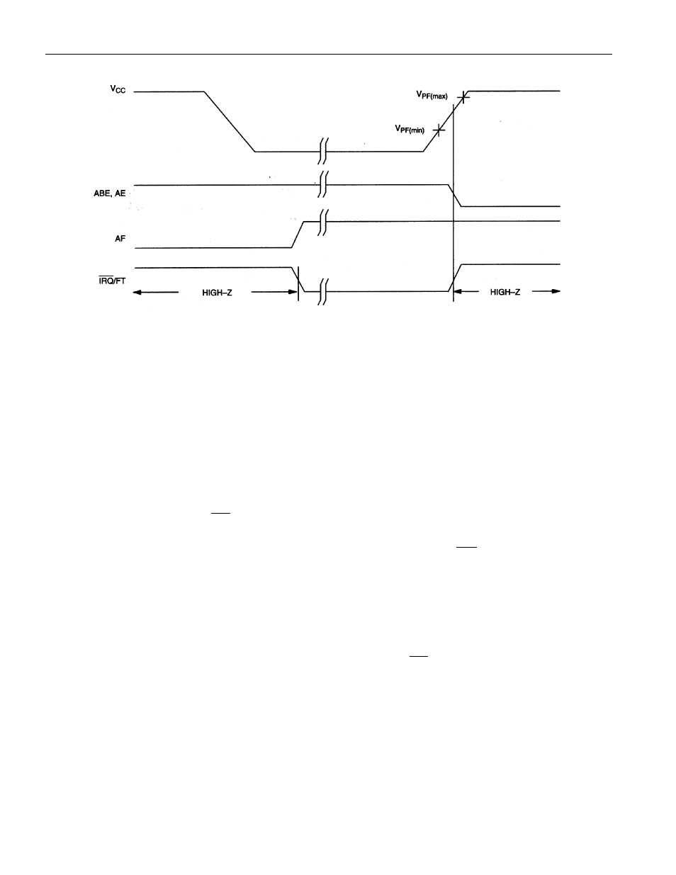
BACK-UP MODE ALARM WAVEFORMS Figure 4
USING THE WATCHDOG TIMER
The watchdog timer can be used to detect an out-of-control processor. The user programs the watchdog
timer by setting the desired amount of time-out into the 8-bit Watchdog Register (Address 1FF7h). The
five Watchdog Register bits BMB4-BMB0 store a binary multiplier and the two lower order bits RB1-
RB0 select the resolution, where 00=1/16 second, 01=1/4 second, 10=1 second, and 11=4 seconds. The
watchdog time-out value is then determined by the multiplication of the 5-bit multiplier value with the 2-
bit resolution value. (For example: writing 00001110 in the watchdog Register = 3 X 1 second or 3
seconds). If the processor does not reset the timer within the specified period, the Watchdog Flag (WF) is
set and a processor interrupt is generated and stays active until either the Watchdog Flag (WF) is read or
the watchdog register (1FF7) is read or written.
The most significant bit of the Watchdog Register is the Watchdog Steering Bit (WDS). When set to a 0,
the watchdog will activate the
IRQ
/FT output when the watchdog times out.
When WDS is set to a 1, the watchdog will output a negative pulse on the
RST
output for a duration of
40 ms to 200 ms. The Watchdog register (1FF7) and the FT bit will reset to a 0 at the end of a watchdog
time-out when the WDS bit is set to a 1.
The watchdog timer resets when the processor performs a read or write of the Watchdog register. The
time-out period then starts over. The watchdog timer is disabled by writing a value of 00h to the
watchdog register. The watchdog function is automatically disabled upon power-up and the Watchdog
register is cleared. If the watchdog function is set to output to the
IRQ
/FT output and the frequency test
function is activated, the watchdog function prevails and the frequency test function is denied.
POWER-ON DEFAULT STATES
Upon application of power to the device, the following register bits are set to 0:
WDS=0, BMB0-BMB4=0, RB0-RB1=0, AE=0, ABE=0.