Rainbow Electronics DS1666S User Manual
Ds1666 audio digital resistor, Features, Pin assignment pin descriptions
1 of 9
102899
FEATURES
128 position, digitally controlled poten-
tiometer
Operates from a +5 volts power supply with
TTL signal inputs
Wide analog voltage range of ±5 volts
Low-power CMOS
14-pin DIP or 16-pin SOIC for surface
mount applications
Default position on power up sets wiper
position to 10% of active digital taps (3% of
the total end-to-end resistance)
Operating temperature range
–
Industrial temp. range: -40°C to +85°C
Resistance/Step
Resistance values Low End High End -3dB Point
DS1666-10 10K 24
ȍ 152ȍ 1.0 MHz
DS1666-50 50K 122
ȍ 759ȍ 200 kHz
DS1666-100 100K 243
ȍ 1.519ȍ 100 kHz
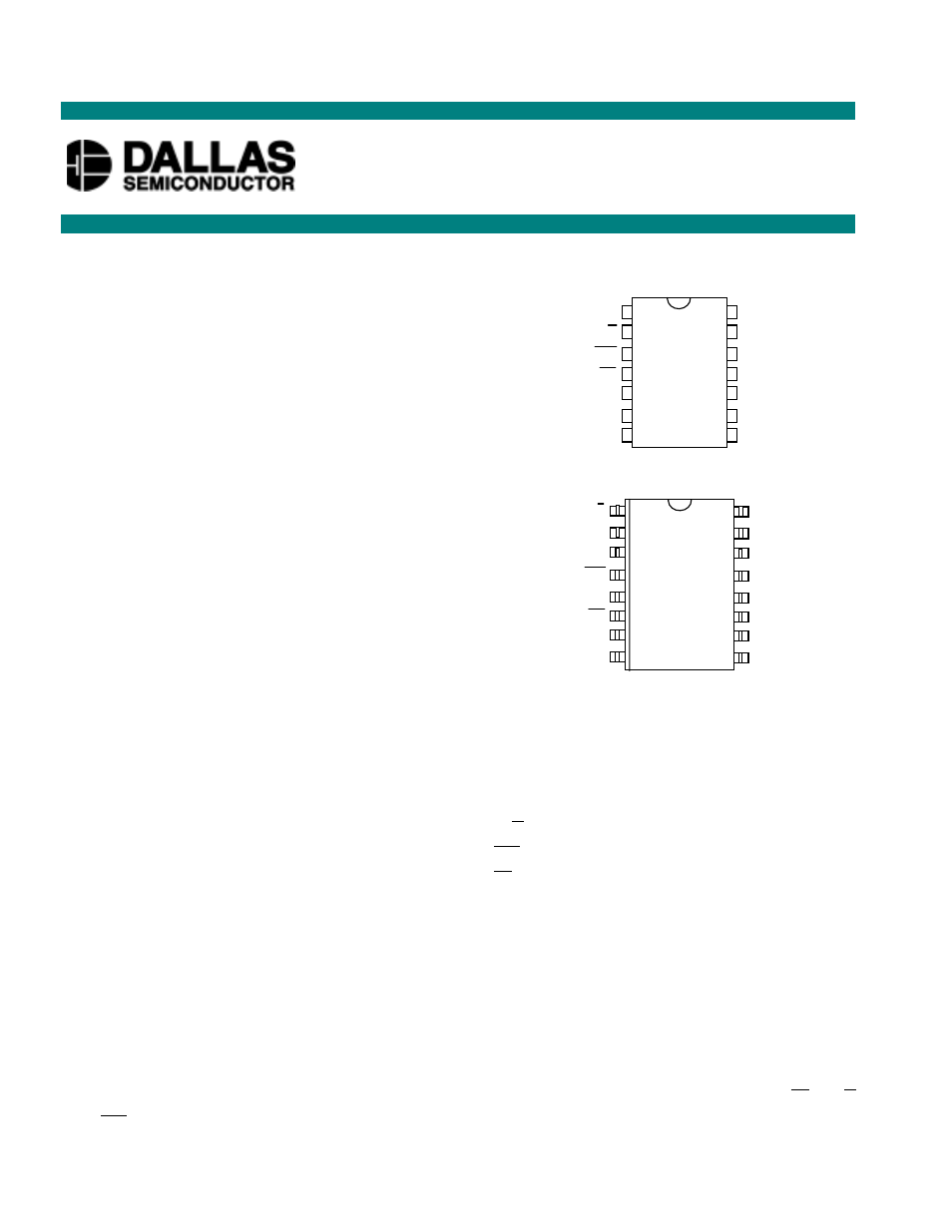
PIN ASSIGNMENT
PIN DESCRIPTIONS
V
H
- High Terminal of Potentiometer
V
L
- Low Terminal of Potentiometer
V
W
- Wiper Terminal of Potentiometer
U/
D
- Up/Down Control
INC
- Wiper Movement Control
CS
- Chip Select for Wiper Movement
NC
- No Connection
V
CC
- 5V Power Supply Input
GND
- Ground
V
B
- Substrate Bias Voltage (0 to -5V)
DESCRIPTION
The DS1666 Audio Digital Resistor is a solid-state potentiometer composed of 127 digitally controlled
resistive elements. Between each resistive section and both ends of the potentiometer are tap points
multiplexed to the wiper. The position of the wiper on the resistance array is controlled by the
CS
, U/
D
and
INC
inputs. The taper of the DS1666 is shown in Figure 1.
DS1666
Audio Digital Resistor
www.dalsemi.com
NC
U/D
INC
CS
GND
NC
NC
14
13
12
11
10
9
8
NC
V
CC
V
B
V
W
V
H
V
L
NC
1
2
3
4
5
6
7
14-PIN DIP (300 MIL)
See Mech. Drawings Section
16-PIN SOIC (300 MIL)
See Mech. Drawings Section
U/D
1
16
V
CC
NC
NC
INC
NC
CS
NC
GND
2
3
4
5
6
7
8
15
14
13
12
11
10
9
V
B
V
W
V
H
NC
V
L
NC
NC