Pin description, Typical operating circuit ordering information, Description – Rainbow Electronics DS1244Y User Manual
Page 2: Packages
DS1244/DS1244P
2 of 19
PIN DESCRIPTION
A
0
–A
14
-
Address
Inputs
CE
- Chip Enable
OE
- Output Enable
WE
- Write Enable
V
CC
- Power-Supply Input
GND -
Ground
DQ
0
–DQ
7
- Data In/Data Out
N.C.
- No Connection
X1, X2
- Crystal Connection
V
BAT
- Battery Connection
RST
-
Reset
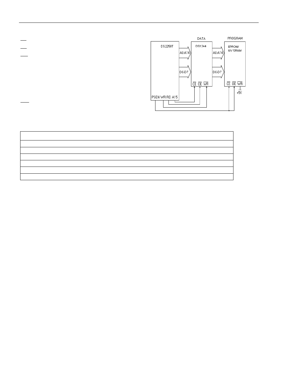
TYPICAL OPERATING CIRCUIT
ORDERING INFORMATION
PART
PIN-PACKAGE
TEMP RANGE
TOP MARK
DS1244Y-70
28-Module (740mil)
0°C to +70°C
DS1244Y-70
DS1244YP-70
34-PowerCap
*
0°C to +70°C
DS1244YP-70
DS1244W-120
28-Module (740mil)
0°C to +70°C
DS1244W-120
DS1244W-120IND
28-Module (740mil)
-40°C to +85°C
DS1244W-120IND
DS1244WP-120
34-PowerCap
*
0°C to +70°C
DS1244WP-120
DS1244WP-120IND 34-PowerCap
*
-40°C to +85°C
DS1244WP-120IND
*
DS9034PCX (PowerCap) Required. (Must be ordered separately.)
DESCRIPTION
The DS1244 256k NV SRAM with a Phantom clock is a fully static nonvolatile RAM (NV SRAM)
(organized as 32k words by 8 bits) with a built-in real-time clock. The DS1244 has a self-contained
lithium energy source and control circuitry, which constantly monitors V
CC
for an out-of-tolerance
condition. When such a condition occurs, the lithium energy source is automatically switched on and
write protection is unconditionally enabled to prevent garbled data in both the memory and real-time
clock.
The phantom clock provides timekeeping information for hundredths of seconds, seconds, minutes, hours,
days, date, months, and years. The date at the end of the month is automatically adjusted for months with
fewer than 31 days, including correction for leap years. The phantom clock operates in either 24-hour or
12-hour format with an AM/PM indicator.
PACKAGES
The DS1244 is available in two packages: 28-pin DIP and 34-pin PowerCap module. The 28-pin DIP-
style module integrates the crystal, lithium energy source, and silicon all in one package. The 34-pin
PowerCap module board is designed with contacts for connection to a separate PowerCap (DS9034PCX)
that contains the crystal and battery. This design allows the PowerCap to be mounted on top of the
DS1244P after the completion of the surface mount process. Mounting the PowerCap after the surface
mount process prevents damage to the crystal and battery due to the high temperatures required for solder
reflow. The PowerCap is keyed to prevent reverse insertion. The PowerCap module board and PowerCap
are ordered separately and shipped in separate containers. The part number for the Powercap is
DS9034PCX.