Ds3231, Extremely accurate i, C-integrated rtc/tcxo/crystal – Rainbow Electronics DS3231 User Manual
Page 12: Alarms, Table 2. alarm mask bits
DS3231
The countdown chain is reset whenever the seconds
register is written. Write transfers occur on the acknowl-
edge from the DS3231. Once the countdown chain is
reset, to avoid rollover issues the remaining time and
date registers must be written within 1 second. The 1Hz
square-wave output, if enabled, transitions high 500ms
after the seconds data transfer, provided the oscillator
is already running.
Alarms
The DS3231 contains two time-of-day/date alarms.
Alarm 1 can be set by writing to registers 07h to 0Ah.
Alarm 2 can be set by writing to registers 0Bh to 0Dh.
The alarms can be programmed (by the alarm enable
and INTCN bits of the control register) to activate the
INT/SQW output on an alarm match condition. Bit 7 of
each of the time-of-day/date alarm registers are mask
bits (Table 2). When all the mask bits for each alarm
are logic 0, an alarm only occurs when the values in the
timekeeping registers match the corresponding values
stored in the time-of-day/date alarm registers. The
alarms can also be programmed to repeat every sec-
ond, minute, hour, day, or date. Table 2 shows the pos-
sible settings. Configurations not listed in the table will
result in illogical operation.
The DY/DT bits (bit 6 of the alarm day/date registers)
control whether the alarm value stored in bits 0 to 5 of
that register reflects the day of the week or the date of
the month. If DY/DT is written to logic 0, the alarm will
be the result of a match with date of the month. If
DY/DT is written to logic 1, the alarm will be the result of
a match with day of the week.
When the RTC register values match alarm register set-
tings, the corresponding Alarm Flag ‘A1F’ or ‘A2F’ bit is
set to logic 1. If the corresponding Alarm Interrupt
Enable ‘A1IE’ or ‘A2IE’ is also set to logic 1 and the
INTCN bit is set to logic 1, the alarm condition will acti-
vate the INT/SQW signal. The match is tested on the
once-per-second update of the time and date registers.
Extremely Accurate I
2
C-Integrated
RTC/TCXO/Crystal
12
____________________________________________________________________
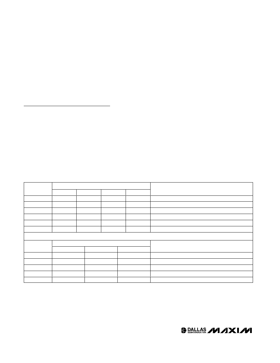
Table 2. Alarm Mask Bits
ALARM 1 REGISTER MASK BITS (BIT 7)
DY/
DT
A1M4
A1M3
A1M2
A1M1
ALARM RATE
X
1
1
1
1
Alarm once per second
X
1
1
1
0
Alarm when seconds match
X
1
1
0
0
Alarm when minutes and seconds match
X
1
0
0
0
Alarm when hours, minutes, and seconds match
0
0
0
0
0
Alarm when date, hours, minutes, and seconds match
1
0
0
0
0
Alarm when day, hours, minutes, and seconds match
ALARM 2 REGISTER MASK BITS (BIT 7)
DY/
DT
A2M4
A2M3
A2M2
ALARM RATE
X
1
1
1
Alarm once per minute (00 seconds of every minute)
X
1
1
0
Alarm when minutes match
X
1
0
0
Alarm when hours and minutes match
0
0
0
0
Alarm when date, hours, and minutes match
1
0
0
0
Alarm when day, hours, and minutes match