Ds4412 dual-channel, i, C adjustable sink/source current dac, C communication – Rainbow Electronics DS4412 User Manual
Page 8
read sequence or as an indication that the device is
not receiving data.
Byte Write: A byte write consists of 8 bits of informa-
tion transferred from the master to the slave (most sig-
nificant bit first) plus a 1-bit acknowledgement from
the slave to the master. The 8 bits transmitted by the
master are done according to the bit-write definition,
and the acknowledgement is read using the bit-read
definition.
Byte Read: A byte read is an 8-bit information trans-
fer from the slave to the master plus a 1-bit ACK or
NACK from the master to the slave. The 8 bits of
information that are transferred (most significant bit
first) from the slave to the master are read by the
master using the bit read definition above, and the
master transmits an ACK using the bit write defini-
tion to receive additional data bytes. The master
must NACK the last byte read to terminated commu-
nication so the slave will return control of SDA to the
master.
Slave Address Byte: Each slave on the I
2
C bus
responds to a slave address byte sent immediately fol-
lowing a START condition. The slave address byte
contains the slave address in the most significant 7
bits and the R/W bit in the least significant bit. The
DS4412’s slave address is 90h.
When the R/W bit is 0 (such as in 90h), the master is
indicating it will write data to the slave. If R/W = 1
(91h in this case), the master is indicating it wants to
read from the slave. If an incorrect slave address is
written, the DS4412 assumes the master is commu-
nicating with another I
2
C device and ignores the
communication until the next START condition is
sent.
Memory Address: During an I
2
C write operation,
the master must transmit a memory address to iden-
tify the memory location where the slave is to store
the data. The memory address is always the second
byte transmitted during a write operation following
the slave address byte.
I
2
C Communication
Writing to a Slave: The master must generate a START
condition, write the slave address byte (R/W = 0), write
the memory address, write the byte of data, and gener-
ate a STOP condition. Remember that the master must
read the slave’s acknowledgement during all byte-write
operations.
Reading from a Slave: To read from the slave, the
master generates a START condition, writes the slave
address byte with R/W = 1, reads the data byte with a
NACK to indicate the end of the transfer, and generates
a STOP condition.
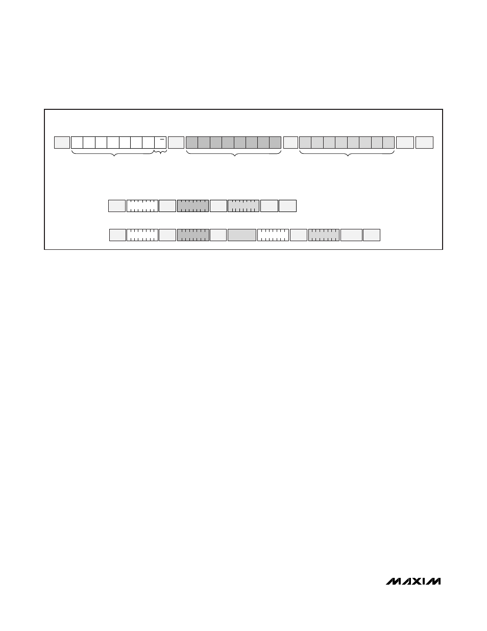
SLAVE
ADDRESS
START
START
1
0
0
1
0
0
0
R/W
SLAVE
ACK
SLAVE
ACK
SLAVE
ACK
MSB
LSB
MSB
LSB
MSB
LSB
b7
b6
b5
b4
b3
b2
b1
b0
READ/
WRITE
REGISTER/MEMORY ADDRESS
b7
b6
b5
b4
b3
b2
b1
b0
DATA
STOP
SINGLE BYTE WRITE
-WRITE RESISTOR
F9h TO 00h
SINGLE BYTE READ
-READ RESISTOR F8h
START
REPEATED
START
90h
MASTER
NACK
STOP
1 0 0 1 0 0 0 0
1 1 1 1 1 0 0 0
F8h
1 0 0 1 0 0 0 1
1 0 0 1 0 0 0 0
1 1 1 1 1 0 0 1
90h
F9h
STOP
DATA
EXAMPLE I
2
C TRANSACTIONS
TYPICAL I
2
C WRITE TRANSACTION
0 0 0 0 0 0 0 0
90h
A)
B)
SLAVE
ACK
SLAVE
ACK
SLAVE
ACK
SLAVE
ACK
SLAVE
ACK
SLAVE
ACK
Figure 2. I
2
C Communication Examples
DS4412
Dual-Channel, I
2
C Adjustable
Sink/Source Current DAC
8
_______________________________________________________________________________________