Ds4412 dual-channel, i, C adjustable sink/source current dac, Output current characteristics (continued) – Rainbow Electronics DS4412 User Manual
Page 3: C ac electrical characteristics
DS4412
Dual-Channel, I
2
C Adjustable
Sink/Source Current DAC
_______________________________________________________________________________________
3
Note 1: All voltages with respect to ground, currents entering the IC are specified positive and currents exiting the IC are negative.
Note 2: Supply current specified with all outputs set to zero current setting with all inputs driven to well-defined logic levels. SDA and
SCL are connected to V
CC
. Excludes current through R
FS
resistors (I
RFS
). Total current includes I
CC
+ 2.5 x (I
RFS0
+ I
RFS0
).
Note 3: The output voltage range must be satisfied to ensure the device meets its accuracy and linearity specifications.
Note 4: Input resistors R
FS
must be between 2.25k
Ω and 9.0kΩ to ensure the device meets its accuracy and linearity specifications.
Note 5: Temperature drift excludes drift caused by external resistor.
Note 6: Differential linearity is defined as the difference between the expected incremental current increase with respect to position
and the actual increase. The expected incremental increase is the full-scale range divided by 15.
Note 7: Integral linearity is defined as the difference between the expected value as a function of the setting and the actual value.
The expected value is a straight line between the zero and the full-scale values proportional to the setting.
Note 8: Timing shown is for fast-mode (400kHz) operation. This device is also backward compatible with I
2
C standard-mode timing.
Note 9: C
B
—total capacitance of one bus line in pF.
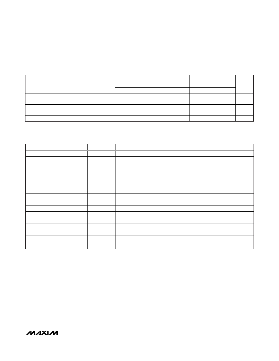
OUTPUT CURRENT CHARACTERISTICS (continued)
(V
CC
= +2.7V to +5.5V, TA = -40°C to +85°C.)
PARAMETER SYMBOL
CONDITIONS
MIN
TYP
MAX
UNITS
DC source, V
OUT
measured at 1.2V
-0.02
Output-Current Variation due to
Output Voltage Change
DC sink, V
OUT
measured at 1.2V
+0.12
%/V
Output Leakage Current at Zero
Current Setting
I
ZERO
-1 +1 μA
Output-Current Differential
Linearity
DNL (Note
6)
0.5 LSB
Output-Current Integral Linearity
INL
(Note 7)
1
LSB
I
2
C AC ELECTRICAL CHARACTERISTICS
(V
CC
= +2.7V to +5.5V, T
A
= -40°C to +85°C.)
PARAMETER
SYMBOL
CONDITIONS
MIN
TYP
MAX
UNITS
SCL Clock Frequency
f
SCL
(Note 8)
0
400
kHz
Bus Free Time Between STOP
and START Conditions
t
BUF
1.3
µs
Hold Time (Repeated) START
Condition
t
HD:STA
0.6
µs
Low Period of SCL
t
LOW
1.3
µs
High Period of SCL
t
HIGH
0.6
µs
Data Hold Time
t
DH:DAT
0
0.9
µs
Data Setup Time
t
SU:DAT
100
ns
START Setup Time
t
SU:STA
0.6
µs
SDA and SCL Rise Time
t
R
(Note 9)
20 +
0.1C
B
300
ns
SDA and SCL Fall Time
t
F
(Note 9)
20 +
0.1C
B
300
ns
STOP Setup Time
t
SU:STO
0.6
µs
SDA and SCL Capacitive Loading
C
B
(Note 9)
400
pF