At89ls53, Timer 0 and 1, Timer 2 – Rainbow Electronics AT89LS53 User Manual
Page 10: Capture mode, Auto-reload (up or down counter)
AT89LS53
4-258
Timer 0 and 1
Timer 0 and Timer 1 in the AT89LS53 operate the same
way as Timer 0 and Timer 1 in the AT89C51, AT89C52 and
AT89C55. For further information, see the October 1995
Microcontroller Data Book, page 2-45, section titled,
“Timer/Counters.”
Timer 2
Timer 2 is a 16 bit Timer/Counter that can operate as either
a timer or an event counter. The type of operation is
selected by bit C/T2 in the SFR T2CON (shown in Table 2).
Timer 2 has three operating modes: capture, auto-reload
(up or down counting), and baud rate generator. The
modes are selected by bits in T2CON, as shown in Table 8.
Timer 2 consists of two 8-bit registers, TH2 and TL2. In the
Timer function, the TL2 register is incremented every
machine cycle. Since a machine cycle consists of 12 oscil-
lator periods, the count rate is 1/12 of the oscillator fre-
quency.
In the Counter function, the register is incremented in
response to a 1-to-0 transition at its corresponding external
input pin, T2. In this function, the external input is sampled
during S5P2 of every machine cycle. When the samples
show a high in one cycle and a low in the next cycle, the
count is incremented. The new count value appears in the
register during S3P1 of the cycle following the one in which
the transition was detected. Since two machine cycles (24
oscillator periods) are required to recognize a 1-to-0 transi-
tion, the maximum count rate is 1/24 of the oscillator fre-
quency. To ensure that a given level is sampled at least
once before it changes, the level should be held for at least
one full machine cycle.
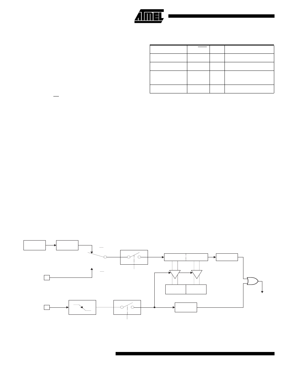
Capture Mode
In the capture mode, two options are selected by bit
EXEN2 in T2CON. If EXEN2 = 0, Timer 2 is a 16 bit timer
or counter which upon overflow sets bit TF2 in T2CON.
This bit can then be used to generate an interrupt. If
EXEN2 = 1, Timer 2 performs the same operation, but a 1-
to-0 transition at external input T2EX also causes the cur-
rent value in TH2 and TL2 to be captured into RCAP2H and
RCAP2L, respectively. In addition, the transition at T2EX
causes bit EXF2 in T2CON to be set. The EXF2 bit, like
TF2, can generate an interrupt. The capture mode is illus-
trated in Figure 1.
Auto-Reload (Up or Down Counter)
Timer 2 can be programmed to count up or down when
configured in its 16 bit auto-reload mode. This feature is
invoked by the DCEN (Down Counter Enable) bit located in
the SFR T2MOD (see Table 9). Upon reset, the DCEN bit
is set to 0 so that timer 2 will default to count up. When
DCEN is set, Timer 2 can count up or down, depending on
the value of the T2EX pin.
Table 8. Timer 2 Operating Modes
RCLK + TCLK
CP/RL2
TR2
MODE
0
0
1
16-bit Auto-Reload
0
1
1
16-bit Capture
1
X
1
Baud Rate
Generator
X
X
0
(Off)
Figure 1. Timer 2 in Capture Mode
OSC
EXF2
T2EX PIN
T2 PIN
TR2
EXEN2
C/T2 = 0
C/T2 = 1
CONTROL
CAPTURE
OVERFLOW
CONTROL
TRANSITION
DETECTOR
TIMER 2
INTERRUPT
÷12
RCAP2L
RCAP2H
TH2
TL2
TF2