Detailed pin description table 2, Operation–thermostat controls – Rainbow Electronics DS1620 User Manual
Page 4
DS1620
4 of 13
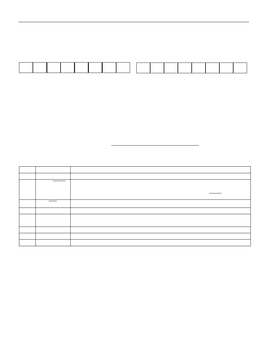
words, with the most significant 7 bits being ignored or set to 0, as illustrated in Table 1. After the MSB,
the DS1620 will output 0s.
Note that temperature is represented in the DS1620 in terms of a ½
°
C LSB, yielding the following 9–bit
format:
Higher resolutions may be obtained by reading the temperature, and truncating the 0.5°C bit (the LSB)
from the read value. This value is TEMP_READ. The value left in the counter may then be read by
issuing a READ COUNTER command. This value is the count remaining (COUNT_REMAIN) after the
gate period has ceased. By loading the value of the slope accumulator into the count register (using the
READ SLOPE command), this value may then be read, yielding the number of counts per degree C
(COUNT_PER_C) at that temperature. The actual temperature may be then be calculated by the user
using the following:
TEMPERATURE=TEMP_READ-0.25 +
C
COUNT_PER_
IN)
COUNT_REMA
-
_C
(COUNT_PER
DETAILED PIN DESCRIPTION Table 2
PIN
SYMBOL
DESCRIPTION
1
DQ
Data Input/Output pin for 3-wire communication port.
2
CLK/
CONV
Clock input pin for 3-wire communication port. When the DS1620 is used in a
stand-alone application with no 3–wire port, this pin can be used as a convert
pin. Temperature conversion will begin on the falling edge of
CONV
.
3
RST
Reset input pin for 3-wire communication port.
4
GND
Ground pin.
5
T
COM
High/Low Combination Trigger. Goes high when temperature exceeds TH;
will reset to low when temperature falls below TL.
6
T
LOW
Low Temperature Trigger. Goes high when temperature falls below TL.
7
T
HIGH
High Temperature Trigger. Goes high when temperature exceeds TH.
8
V
DD
Supply Voltage. 2.7V – 5.5V input power pin.
OPERATION–THERMOSTAT CONTROLS
Three thermally triggered outputs, T
HIGH
, T
LOW
, and T
COM
, are provided to allow the DS1620 to be used
as a thermostat, as shown in Figure 3. When the DS1620’s temperature meets or exceeds the value stored
in the high temperature trip register, the output T
HIGH
becomes active (high) and remains active until the
DS1620’s measured temperature becomes less than the stored value in the high temperature register, TH.
The T
HIGH
output can be used to indicate that a high temperature tolerance boundary has been met or
exceeded, or it can be used as part of a closed loop system to activate a cooling system and deactivate it
when the system temperature returns to tolerance.
The T
LOW
output functions similarly to the T
HIGH
output. When the DS1620’s measured temperature
equals or falls below the value stored in the low temperature register, the T
LOW
output becomes active.
T
LOW
remains active until the DS1620’s temperature becomes greater than the value stored in the low
temperature register, TL. The T
LOW
output can be used to indicate that a low temperature tolerance
X
X
X
X
X
X
X
1
1
1
0
0
1
1
1
0
LSB
T = -25°C
MSB