Isd2100 datasheet – Rainbow Electronics ISD2100 User Manual
Page 8
ISD2100 DATASHEET
Publication Release Feb 9, 2010
- 8 -
Revision 0.51
0
1
2
3
4
5
6
7
0
1
2
3
4
5
6
7
SSB
SCLK
MISO
MOSI
X
C7
C6
C5
X
C4
C3
C2
C1
C0
PD RDY INT FULL X
VG
BSY
BUF
FUL
CMD
BSY
PD RDY INT FULL X
VG
BSY
BUF
FUL
CMD
BSY
D7
D6
D5
D4
D3
D2
D1
D0
Z
X
RDY/BSYB
B
R
T
/
=1
=1
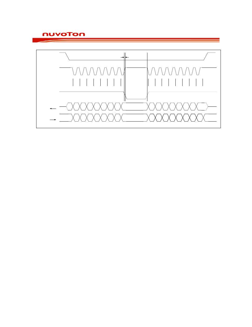
Figure 6-2 RDY/BSYB Timing for SPI Writing Transactions.
If the SCLK does not remain high, RDY bit of the status register will be set to zero and be reported via
the MISO pin so the host can take the necessary actions (i.e., terminate SPI transmission and re-
transmit the data when the RDY/BSYB pin returns to high).
For commands (i.e., DIG_READ, SPI_PCM_READ) that read data from ISD2100, MISO is used to
read the data; therefore, the host must monitor the status via the RDY/BSYB pin and take the
necessary actions.
The INT pin will go low to indicate (1) data overrun/overflow when sending data to the ISD2100; or (2)
invalid data from ISD2100. See Figure 6-3 for the timing diagram.