Figure 4-2, Atr0622 [preliminary – Rainbow Electronics ATR0622 User Manual
Page 18
18
4891CS–GPS–01/06
ATR0622 [Preliminary]
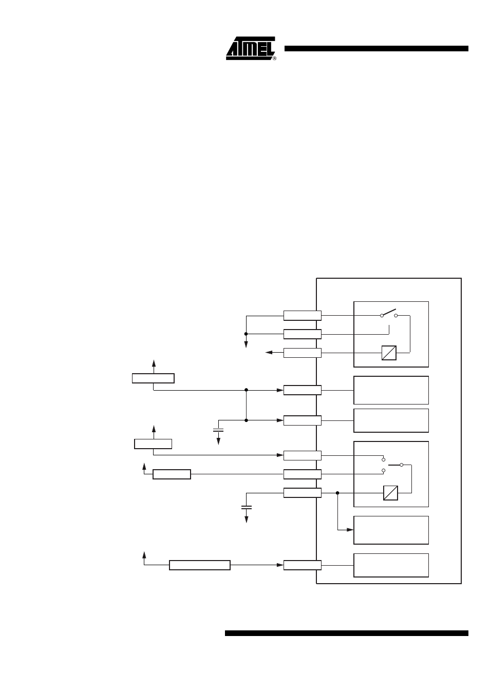
The baseband IC contains a built in low dropout voltage regulator LDO18. This regulator can
be used if the host system does not provide the core voltage VDD18 of 1.8V nominal. In such
case, LDO18 will provide a 1.8V supply voltage from any input voltage VDD between 2.3V and
3.6V. The LDO_EN input can be used to shut down VDD18 if the system is in standby mode.
If the host system does however supply a 1.8V core voltage directly, this voltage has to be
connected to the VDD18 supply pins of the baseband IC. LDO_EN must be connected to
GND. LDO_IN can be connected to GND. LDO_OUT must not be connected.
A second built in low dropout voltage regulator LDOBAT provides the supply voltage for the
RTC and backup SRAM from any input voltage LDOBAT_IN between 2.3V and 3.6V or from
VBAT between 1.5V and 3.6V. The backup battery connected to VBAT is only discharged if
the supply connected to LDOBAT_IN is shut-down.
Only after VDD18 has been supplied to ATR0622 the RTC section will be initialized properly. If
only VBAT is applied first, the current consumption of the RTC and backup SRAM is
undetermined.
Figure 4-2.
External Wiring Example Using 1.8V from Host System and Backup Power
Supply
ATR0622 internal
VDDUSB
0 to 2V or 3V to 3.6V
1.5V to 3.6V
1 µF
(X7R)
ldoout
ldoen
ldoin
LDO18
LDO_IN
1 µF
(X7R)
VDDIO
LDO_EN
VDD18
LDO_OUT
USB SM and
Transceiver
1.8V to 3.3V
variable IO Domain
RTC
Backup Memory
Core
vbat18
vbat
vdd
ldobat_in
LDOBAT
LDOBAT_IN
VBAT
VBAT18
2.3V to 3.6V
1.65V to 1.95V