Rainbow Electronics ATR0635P1 User Manual
Page 22
22
4979D–GPS–06/08
ATR0635P1
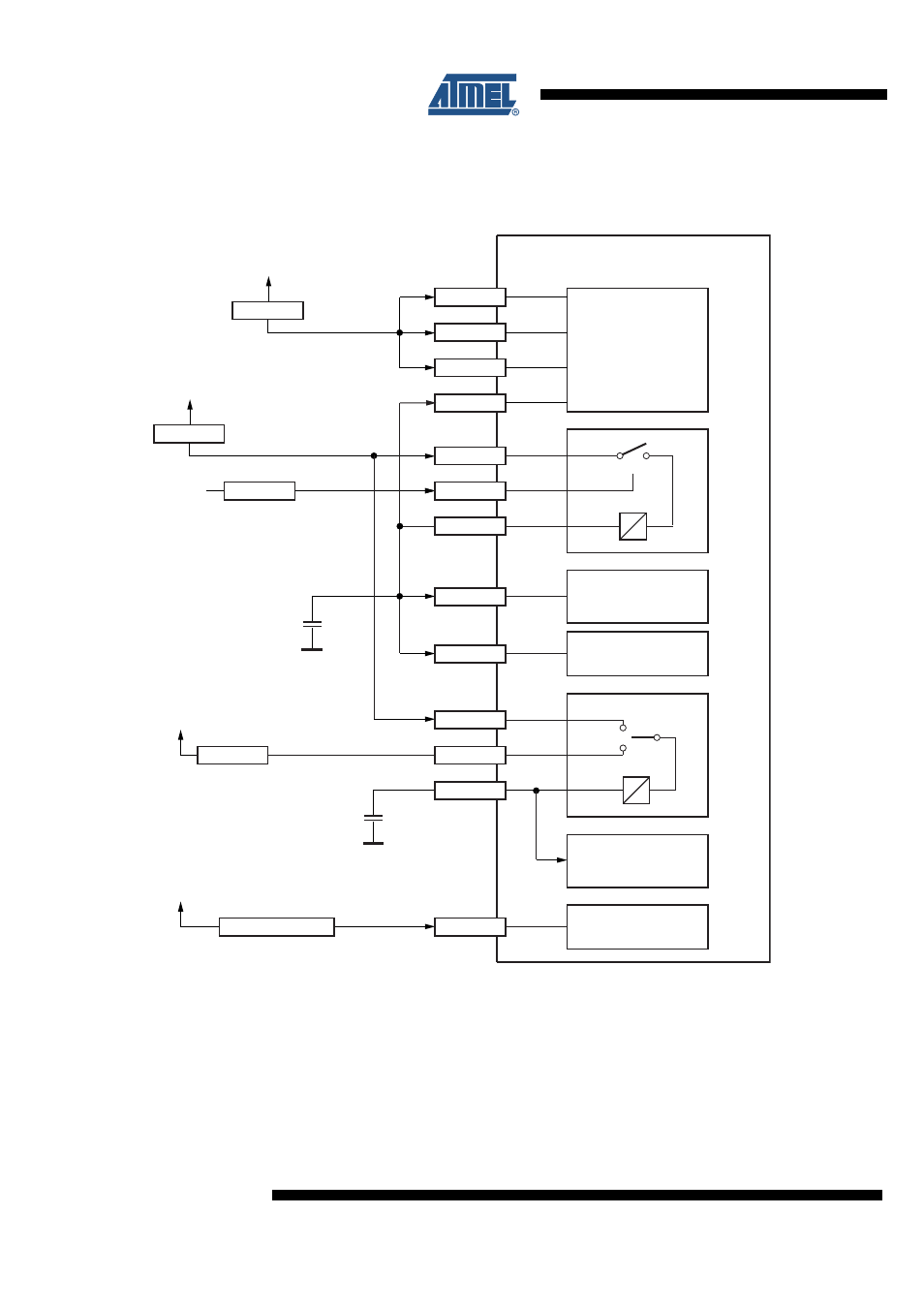
The RTC section will be initialized properly if VDD18 is supplied first to the ATR0635P1. If VBAT
is applied first, the current consumption of the RTC and backup SRAM is undetermined.
Figure 4-2.
Connecting Example: Common Power Supplies for RF and Digital Part Using the Internal LDOs
The USB Transceiver is disabled if VDD_USB < 2.0V. In this case the pins USB_DM and
USB_DP are connected to GND (internal pull-down resistors). The USB Transceiver is enabled
if VDD_USB within 3.0V and 3.6V.
ATR0635P1 internal
VDDUSB
0V or 3V to 3.6V
1.5V to 3.6V
1 µF
(X7R)
ldoout
ldoen
ldoin
LDO18
LDO_IN
1 µF
(X7R)
VDDIO
2.3V to 3.6V
LDO_EN
NSHDN
VDD18
LDO_OUT
USB SM and
transceiver
1.8V to 3.3V
variable I/O domain
RTC
backup memory
Core
vbat18
vbat
VDD
ldobat_in
LDOBAT
LDOBAT_IN
VBAT
VBAT18
RF
VCC1
VCC2
VBP
VDIG
2.7V to 3.3V
- MAX5151 (16 pages)
- MAXQ3108 (64 pages)
- MAX5661 (39 pages)
- MAX6691 (7 pages)
- MAX5362 (12 pages)
- ADC10158 (26 pages)
- MAX8922L (14 pages)
- MAX8596Z (8 pages)
- MAX7491 (18 pages)
- MAX15040 (15 pages)
- MAX5177 (16 pages)
- ADC08138 (22 pages)
- MAX5961 (42 pages)
- T89C51RD2 (86 pages)
- MAX16055 (9 pages)
- MAX6659 (17 pages)
- ADC0820 (20 pages)
- MAX6678 (19 pages)
- MAX8884Z (15 pages)
- MAX16915 (9 pages)
- MAX8620 (18 pages)
- MAX5144 (12 pages)
- MAX6670 (8 pages)
- MAX8760 (39 pages)
- W78C32C (14 pages)
- MX7533 (8 pages)
- MAX8727 (13 pages)
- MAX9053 (15 pages)
- W78C54 (16 pages)
- MAX8614B (15 pages)
- W90N740 (219 pages)
- MAX6626 (13 pages)
- ADC10738 (30 pages)
- MAX17000 (31 pages)
- MAX5051 (21 pages)
- MAXQ1004 (18 pages)
- MAX6871 (51 pages)
- MX7847 (12 pages)
- MAX6608 (6 pages)
- MAX17083 (15 pages)
- MAX6641 (17 pages)
- MAX5251 (16 pages)
- MAX6338 (8 pages)
- MAX6690 (16 pages)
- MAX8668 (18 pages)