1 usb power mode, 2 active antenna supervisor – Rainbow Electronics ATR0635P1 User Manual
Page 15
15
4979D–GPS–06/08
ATR0635P1
The following settings apply if GPSMODE configuration is not enabled, that is, GPSMODE = 0
(ROM defaults):
3.4.1
USB Power Mode
For correct response to the USB host queries, the device has to know its power mode. This is
configured via GPSMODE7. If set to bus powered, an upper current limit of 100 mA is reported
to the USB host; that is, the device classifies itself as a “low-power bus-powered function” with
no more than one USB power unit load.
3.4.2
Active Antenna Supervisor
The two pins P0/NANTSHORT and P15/ANTON plus one pin of P25/NAADET0/MISO or
P14/NAADET1 are always initialized as general purpose I/Os and used as follows:
• P15/ANTON is an output which can be used to switch on and off antenna power supply.
• Input P0/NANTSHORT will indicate an antenna short circuit, i.e. zero DC voltage at the
antenna, to the firmware. If the antenna is switched off by output P15/ANTON, it is assumed
that also input P0/NANTSHORT will signal zero DC voltage, i.e. switch to its active low state.
• Input P25/NAADET0/MISO or P14/NAADET1 will indicate a DC current into the antenna. In
case of short circuit, both P0 and P25/P14 will be active, i.e. at low level. If the antenna is
switched off by output P15/ANTON, it is assumed that also input P25/NAADET0/MISO will
signal zero DC current, i.e. switch to its active low state. Which pin is used as NAADET (P14
or P25) depends on the settings of GPSMODE11 and GPSMODE10 (see
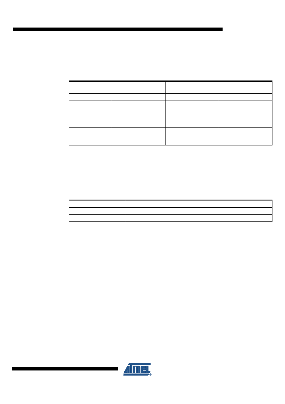
Table 3-11.
Serial I/O Default Setting if GPSMODE Configuration is Deselected
(GPSMODE0 = 0)
USB
NMEA
USART1
NMEA
USART2
UBX
Baud rate (kBaud)
57.6
57.6
Input protocol
UBX, NMEA
UBX, NMEA, RTCM
UBX, NMEA, RTCM
Output protocol
NMEA
NMEA
UBX
Messages
GGA, RMC, GSA, GSV
GGA, RMC, GSA, GSV
NAV: SOL, SVINFO
MON: EXCEPT
Information
messages (UBX INF
or NMEA TXT)
User Notice, Warning,
Error
User, Notice, Warning,
Error
User, Notice, Warning,
Error
Table 3-12.
USB Power Modes
GPSMODE7 (Reset = PU) Description
0
USB device is bus-powered (maximum current limit 100 mA)
1
(1)
USB device is self-powered (default ROM value)
Note:
1. Leave open