Timing diagrams figure 9 – Rainbow Electronics DS1267 User Manual
Page 10
DS1267
10 of 12
102199
4. Relative linearity is used to determine the change in voltage between successive tap positions. Device
test limits ±0.5 LSB.
5. Typical values are for T
A
= 25°C and nominal supply voltage.
6. -3 dB cutoff frequency characteristics for the DS1267 depend on potentiometer total resistance:
DS1267-010: 1 MHz; DS1267-050: 200 kHz; DS1267-100: 100 kHz.
7. C
OUT
is active regardless of the state of
RST
.
8. See Figure 9(a), (b), and (c).
9. See Figure 11.
10. Valid at 25
°C only.
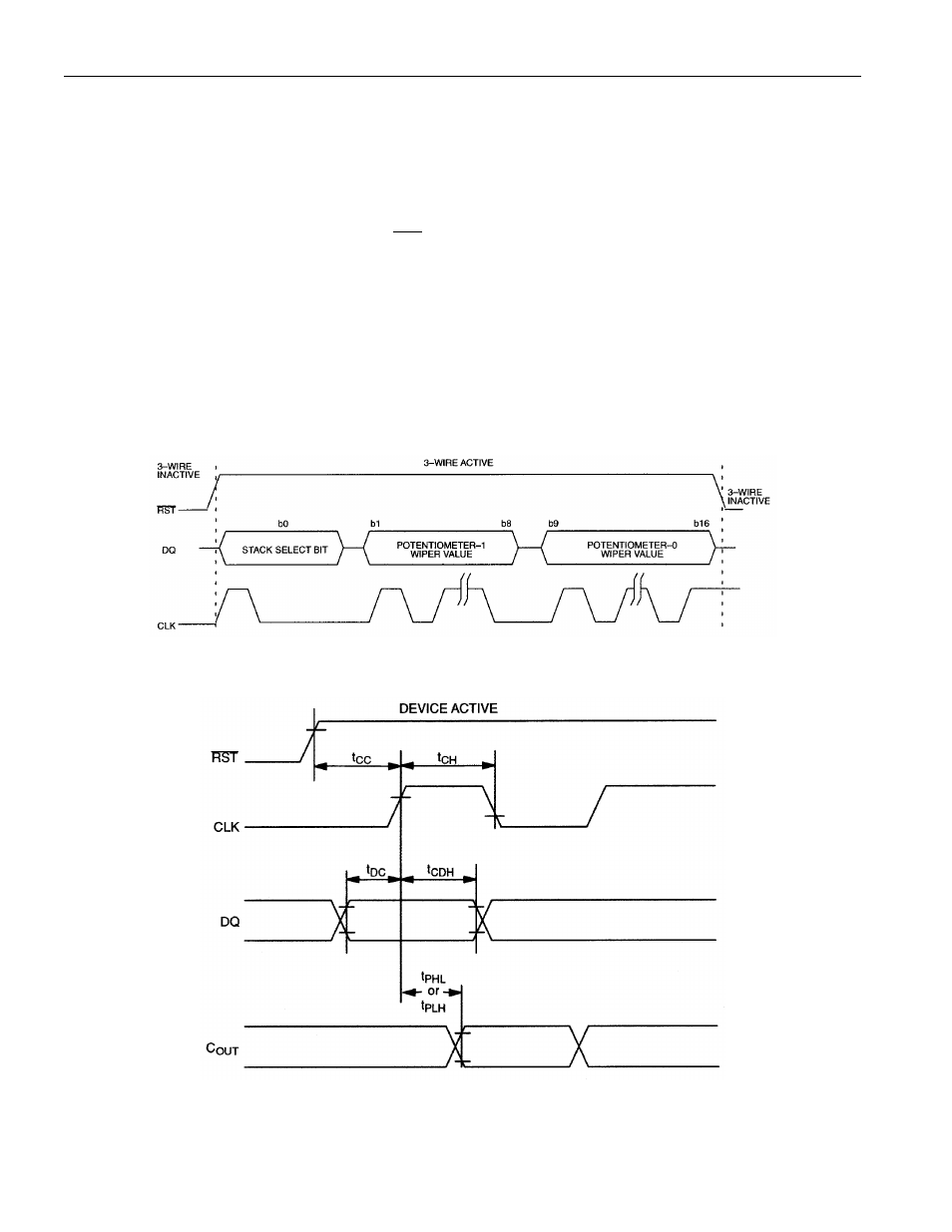
TIMING DIAGRAMS Figure 9
(A) 3-WIRE SERIAL INTERFACE GENERAL OVERVIEW
(B) START OF COMMUNICATION TRANSACTION
See also other documents in the category Rainbow Electronics Computer hardware:
- MAX6869 (17 pages)
- TNY-A9260-C01 (5 pages)
- MAX34441 (53 pages)
- MAX4912 (13 pages)
- QIL-A9260-C11 (20 pages)
- QIL-A9260-C11 (1 page)
- QIL-A9260-C11 (34 pages)
- USB-A9263-C02 (1 page)
- DAB-GPS-C01 (15 pages)
- DAB-GPS-C01 (28 pages)
- DAB-CAM-C01 (27 pages)
- DAB-WLS-C01 (WiFi) (20 pages)
- USB-A9G20-C01 (1 page)
- MAX34440 (43 pages)
- SBC35-A9260-C12 (28 pages)
- SBC35-A9260-C12 (1 page)
- MAX16024 (17 pages)
- USB-A9G20-C11 (5 pages)
- DAB-IMU-C01 (20 pages)
- MAX16021 (21 pages)
- DAB-WLS-C11 (BlueTooth) (2 pages)
- SBC35-A9G20-C11 (24 pages)
- MAX16054 (9 pages)
- MAX14525 (7 pages)
- MAX16066 (61 pages)
- USB-A9260-C12 (1 page)
- DS1803 (11 pages)
- DS12887A (2 pages)
- DS1339 (18 pages)
- DS1858 (22 pages)
- DS12С887A (2 pages)
- DS1804 (7 pages)
- DS1091L (6 pages)
- DS1669S (10 pages)
- DS1867 (14 pages)
- DS1087L (12 pages)
- DS4026 (13 pages)
- DS1286 (13 pages)
- DS1801 (10 pages)
- DS1254 (17 pages)
- DS17887 (38 pages)
- DS1691 (4 pages)
- DS1615 (24 pages)
- DS1868 (14 pages)