Figure 6. setting precision reference voltages, 0 power supply considerations, 0 the adc10321 clock – Rainbow Electronics ADC10321 User Manual
Page 15: Figure 6, Applications information
Applications Information
(Continued)
3.0 POWER SUPPLY CONSIDERATIONS
A/D converters draw sufficient transient current to corrupt
their own power supplies if not adequately bypassed. A 10µF
to 50µF tantalum or aluminum electrolytic capacitor should
be placed within an inch (2.5 centimeters) of the A/D power
pins, with a 0.1µF ceramic chip capacitor placed as close as
possible to each of the converter’s power supply pins. Lead-
less chip capacitors are preferred because they have low
lead inductance.
While a single voltage source should be used for the analog
and digital supplies of the ADC10321, this supply should not
be the supply that is used for other digital circuitry on the
board.
As is the case with all high speed converters, the ADC10321
should be assumed to have little high frequency power sup-
ply rejection. A clean analog power source should be used.
No pin should ever have a voltage on it that is in excess of
the supply voltages or below ground, not even on a transient
basis. This can be a problem upon application of power to a
circuit. Be sure that the supplies to circuits driving the CLK,
PD, OE, analog input and reference pins do not come up any
faster than does the voltage at the ADC10321 power pins.
4.0 THE ADC10321 CLOCK
Although the ADC10321 is tested and its performance is
guaranteed with a 20MHz clock, it typically will function with
clock frequencies from 1MHz to 25MHz. Performance is best
if the clock rise and fall times are 5ns or less.
If the CLK signal is interrupted, or its frequency is too low,
the charge on internal capacitors can dissipate to the point
where the accuracy of the output data will degrade. This is
what limits the minimum sample rate.
The duty cycle of the clock signal can affect the performance
of the A/D Converter. Because achieving a precise duty
cycle is difficult, this device is designed to maintain perfor-
mance over a range of duty cycles. While it is specified and
performance is guaranteed with a 50% clock duty cycle,
performance is typically maintained over a clock duty cycle
range of 45% to 55%.
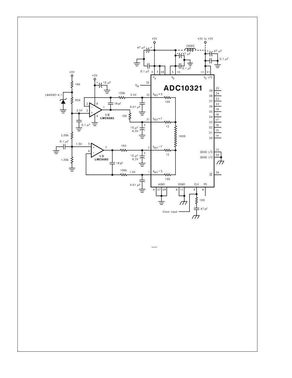
10089720
FIGURE 6. Setting precision reference voltages
ADC10321
www.national.com
15