Functional description, Applications information – Rainbow Electronics ADC0848 User Manual
Page 8
Functional Description
The ADC0844 and ADC0848 contain a 4-channel and 8-
channel analog input multiplexer (MUX) respectively Each
MUX can be configured into one of three modes of opera-
tion differential
pseudo-differential
and single ended
These modes are discussed in the Applications Information
Section The specific mode is selected by loading the MUX
address latch with the proper address (see Table I and Ta-
ble II) Inputs to the MUX address latch (MA0-MA4) are
common with data bus lines (DB0-DB4) and are enabled
when the RD line is high A conversion is initiated via the CS
and WR lines If the data from a previous conversion is not
read the INTR line will be low The falling edge of WR will
reset the INTR line high and ready the A D for a conversion
cycle The rising edge of WR with RD high strobes the data
on the MA0 DB0-MA4 DB4 inputs into the MUX address
latch to select a new input configuration and start a conver-
sion If the RD line is held low during the entire low period of
WR the previous MUX configuration is retained and the
data of the previous conversion is the output on lines DB0-
DB7 After the conversion cycle (t
C
s
40 ms) which is set
by the internal clock frequency the digital data is trans-
ferred to the output latch and the INTR is asserted low
Taking CS and RD low resets INTR output high and outputs
the conversion result on the data lines (DB0-DB7)
Applications Information
1 0 MULTIPLEXER CONFIGURATION
The design of these converters utilizes a sampled-data
comparator structure which allows a differential analog input
to be converted by a successive approximation routine
The actual voltage converted is always the difference be-
tween an assigned ‘‘a’’ input terminal and a ‘‘b’’ input ter-
minal The polarity of each input terminal of the pair being
converted indicates which line the converter expects to be
the most positive If the assigned ‘‘a’’ input is less than the
‘‘b’’ input the converter responds with an all zeros output
code
A unique input multiplexing scheme has been utilized to pro-
vide multiple analog channels The input channels can be
software configured into three modes differential single-
TABLE I ADC0844 MUX ADDRESSING
MUX Address
CS
WR
RD
Channel
MUX
MA3
MA2
MA1
MA0
CH1
CH2
CH3
CH4
AGND
Mode
X
L
L
L
L
H
a
b
X
L
L
H
L
H
b
a
Differential
X
L
H
L
L
H
a
b
X
L
H
H
L
H
b
a
L
H
L
L
L
H
a
b
L
H
L
H
L
H
a
b
Single-Ended
L
H
H
L
L
H
a
b
L
H
H
H
L
H
a
b
H
H
L
L
L
H
a
b
Pseudo-
H
H
L
H
L
H
a
b
Differential
H
H
H
L
L
H
a
b
X
X
X
X
L
L
Previous Channel Configuration
X
e
don’t care
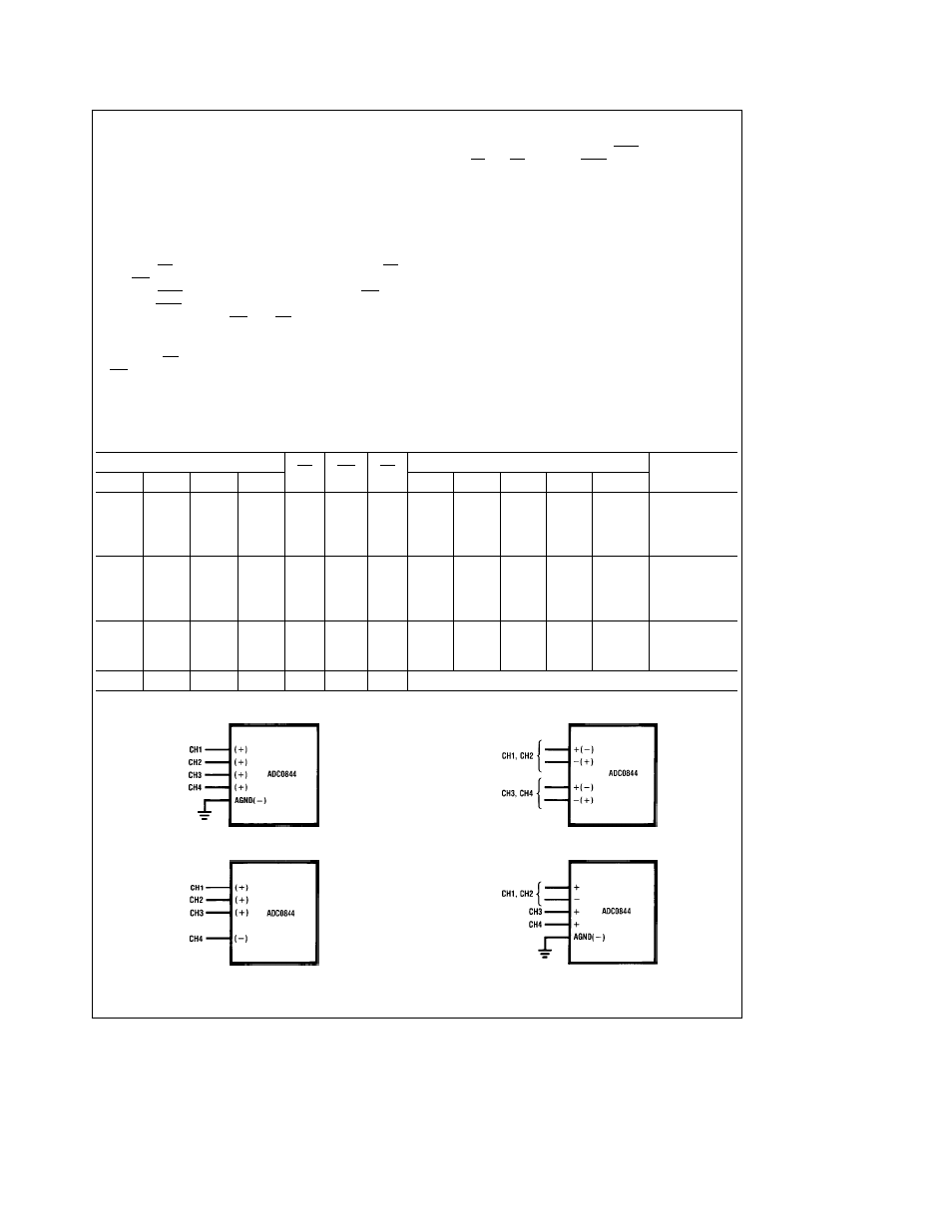
4 Single-Ended
TL H 5016 – 12
2 Differential
TL H 5016 – 13
3 Pseudo-Differential
TL H 5016 – 14
Combined
TL H 5016 – 15
FIGURE 1 Analog Input Multiplexer Options
8