Pin description – Rainbow Electronics MAX5043 User Manual
Page 10
MAX5042/MAX5043
Two-Switch Power ICs with Integrated
Power MOSFETs and Hot-Swap Controller
10
______________________________________________________________________________________
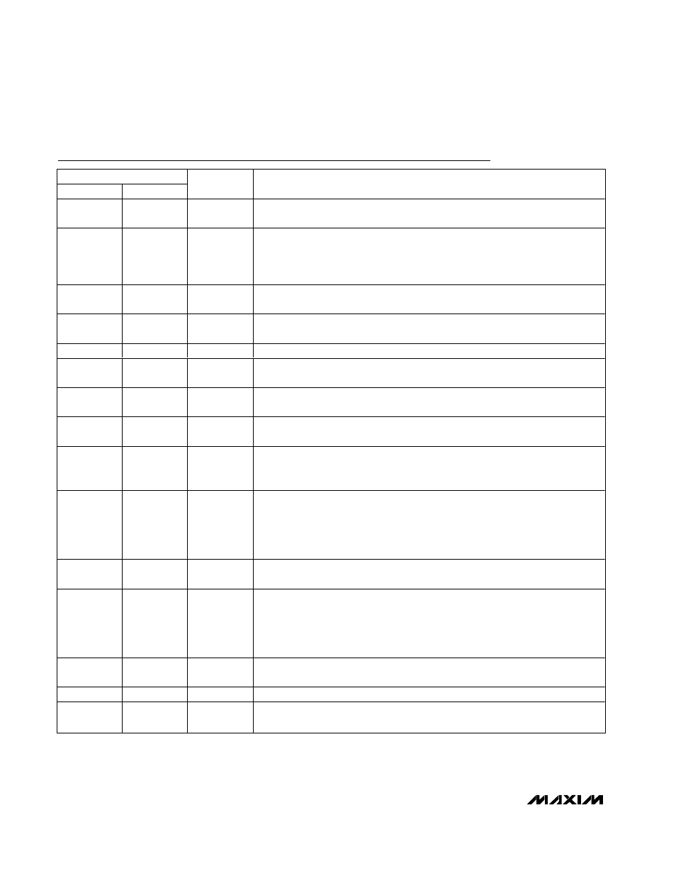
Pin Description
PIN
MAX5042
MAX5043
NAME
FUNCTION
1, 2, 14, 15,
40, 42–45, 56
1, 2, 14, 15,
40, 42–45, 56
N.C.
No Connection. Not internally connected.
3
3
RCFF
Voltage-Mode PWM Ramp. Connect a resistor to the input supply and a capacitor to
PWMNEG for input voltage feed-forward. Input voltage feed-forward provides
instantaneous input-voltage transient rejection and constant loop gain with varying
input voltage.
4
4
RAMP
PWM Ramp Input. For voltage-mode control, connect RAMP to RCFF. For current-
mode control, connect RAMP to CSOUT, the output of the current-sense amplifier.
5
5
OPTO
Inverting Input of the PWM Comparator. Connect OPTO to the collector of the
optotransistor. Connect a pullup resistor from OPTO to REG5.
6
6
CSS
Soft-Start. Connect a capacitor from CSS to PWMNEG to soft-start the converter.
7
7
BST
Boost-Capacitor Bypass for High-Side MOSFET Gate Drive. Connect a 0.1µF
capacitor from BST to XFRMRH for the internal high-side MOSFET driver.
8
8
DRVIN
Low-Side MOSFET Driver Supply. Bypass DRVIN with a 0.22µF capacitor to
PWMPNEG.
9
9
PWMPNEG
Low-Side MOSFET Driver Return. Connect PWMPNEG externally to PWMNEG with a
short trace.
10
10
RCOSC
Oscillator Timing Resistor and Capacitor Connection. Connect a capacitor from
RCOSC to PWMNEG and a resistor from RCOSC to REG5. The switching frequency
is half the frequency of the sawtooth signal at this connection.
11
11
FLTINT
Fault Integration Input. Use FLTINT in addition to cycle-by-cycle current limit. During
persistent current-limit faults, a capacitor connected to FLTINT charges with an
internal 80µA current source. Switching terminates when the voltage reaches 2.7V.
An external resistor connected in parallel discharges the capacitor. Switching
resumes when the voltage drops to 1.8V.
12
12
SYNC
Synchronization Input. The switching frequency of the power supply is half the
synchronization frequency, ensuring less than 50% maximum duty cycle.
13
13
PWMSD
Latched Shutdown Input. Pull PWMSD low with respect to PWMNEG to stop
switching. To restart, release PWMSD and cycle the input supply. Do not leave
PWMSD unconnected. Use PWMSD to prevent catastrophic secondary rectifier
overheating by monitoring the temperature and issuing a shutdown command with
an optocoupler. Connect PWMSD to REG5 when not used.
16, 17, 20,
21, 24
16, 17, 20,
21, 24
SRC
Source Connection for the Internal Low-Side Power MOSFET. Connect SRC to
PWMPNEG with a low-value resistor for current limiting.
18, 19, 22, 23
18, 19, 22, 23
XFRMRL
Low-Side Connection for the Isolation Transformer
25
—
POSINHS
Hot-Swap Controller Positive Input Supply (MAX5042 Only). Connect POSINHS
along with POSINPWM to the most positive rail of the input supply.