Rainbow Electronics MAX16822B User Manual
Page 8
MAX16822A/MAX16822B
2MHz, High-Brightness LED Drivers with
Integrated MOSFET and High-Side Current Sense
8
_______________________________________________________________________________________
Freewheeling-Diode Selection
For stability and best efficiency, a low forward-voltage
drop diode with fast reverse-recovery time and low
capacitance is recommended. A Schottky diode is a
good choice as long as its breakdown voltage is high
enough to withstand the maximum operating voltage.
PCB Layout Guidelines
Careful PCB layout is critical to achieve low switching
losses and stable operation. Use a multilayer board
whenever possible for better noise immunity. Minimize
ground noise by connecting high-current ground
returns, the input bypass-capacitor ground lead, and
the output-filter ground lead to a single point (star
ground configuration). In normal operation, there are two
power loops. One is formed when the internal MOSFET
is on and the high current flows through IN, R
SENSE
,
LED load, the inductor, the internal MOSFET, and GND.
The other loop is formed when the internal MOSFET is
off and the high-current circulates through R
SENSE
, LED
load, the inductor, and the freewheeling diode. Minimize
each loop area to reduce noise interaction.
Place R
SENSE
as close as possible to CS and IN. For
better noise immunity, a Kelvin connection between CS
and R
SENSE
is strongly recommended.
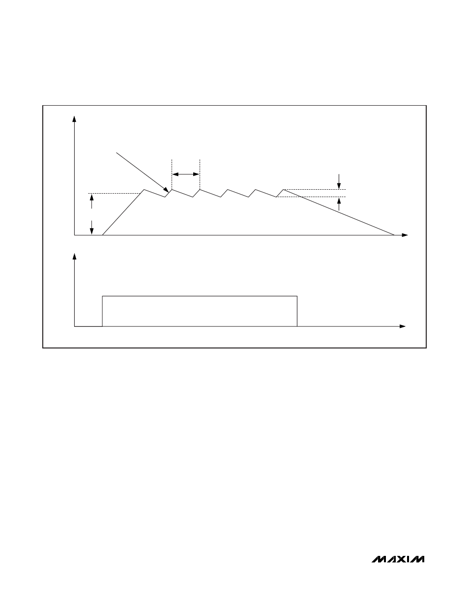
f
SW
t
t
t2
ΔI
t1
AVG. LED
CURRENT
HYSTERETIC
MODE
I
LED
V
DIM
Figure 2. Current-Regulator Operation