Electrical characteristics (continued) – Rainbow Electronics MAX9101 User Manual
Page 3
MAX9100/MAX9101
+1.0V Micropower SOT23 Comparators
_______________________________________________________________________________________
3
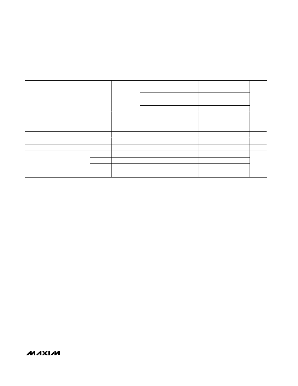
ELECTRICAL CHARACTERISTICS (continued)
(V
CC
= +1.2V to +5.5V, V
CM
= 0, and T
A
= T
MIN
to T
MAX
, unless otherwise noted. Typical values are at T
A
= +25
°C.) (Note 1)
PARAMETER
SYMBOL
CONDITIONS
MIN
TYP
MAX
UNITS
V
CC
= +5.0V
25
Sourcing
(MAX9100)
V
CC
= +1.2V
3
V
CC
= +5.0V
28
Output Short-Circuit Current
I
SC
Sinking
V
CC
= +1.2V
3
mA
Output Open-Drain Leakage
Current (MAX9101)
I
LKG
V
CC
= +5.5V
0.02
0.2
µA
Power-Up Time
t
PU
250
ns
Input Capacitance
C
IN
3
pF
Output Rise Time (MAX9100)
t
rise
C
L
= 15pF
100
ns
Output Fall Time (Note 4)
t
fall
C
L
= 15pF
100
ns
t
pd+
V
OVERDRIVE
= 50mV, V
CC
= +5.0V
3.4
t
pd-
V
OVERDRIVE
= 50mV, V
CC
= +5.0V
4.5
t
pd+
V
OVERDRIVE
= 50mV, V
CC
= +1.0V
3.3
Propagation Delay (Note 5)
t
pd-
V
OVERDRIVE
= 50mV, V
CC
= +1.0V
3.7
µs
Note 1: All specifications are 100% production tested at T
A
= +25
°C. All temperature limits are guaranteed by design.
Note 2: Operation with V
CM
up to V
CC
is possible with reduced accuracy. See Input Stage Circuitry and Rail-to-Rail Operation in
the Applications section for more information.
Note 3: Tested over the specified Input Common-Mode Voltage Range and with V
CC
= +5.5V.
Note 4: Specified with C
L
= 15pF for MAX9100/MAX9101, and with R
PULLUP
= 5k
Ω for MAX9101.
Note 5: Input overdrive is defined above and beyond the offset voltage and hysteresis of the comparator input.