Applications information – Rainbow Electronics MAX16913A User Manual
Page 9
MAX16913/MAX16913A
Remote Antenna Current-Sense
Amplifier and Switches
_______________________________________________________________________________________
9
Applications Information
Choosing the Sense Resistor
Ideally, the maximum load current develops the full-
scale sense voltage across the current-sense resistor.
The current-sense amplifier output voltage is given by:
V
AOUT
(V) = [(V
IN
- V
SENS
)(V) x A
V
(V/V)] + 0.4(V)
where V
AOUT
is the output voltage of the current-sense
amplifier, and A
V
is the gain of the current-sense amplifier
of 13V/V (typ). Calculate the maximum value for R
SENSE
so that the differential voltage across IN and SENS does
not exceed the minimum full-scale sense voltage (87mV):
where V
DIFF(MIN)
= V
IN
- V
SENS
= 87mV minimum at
maximum load current.
Use resistors specified for current-sensing applications
with a minimum resistance value of 0.65Ω, and the
maximum resistance value of 4.7Ω. Keep inductance
low if I
SENSE
has a large high-frequency component.
Wire-wound resistors have the highest inductance,
while metal film is somewhat better. Low-inductance
metal-film resistors are also available. Instead of being
spiral wrapped around a core, as in metal-film or wire-
wound resistors, they are a straight band of metal and
are available in values under 1Ω. Because of the high
current that flows through R
SENSE
, avoid parasitic trace
resistance from causing errors in the sense voltage.
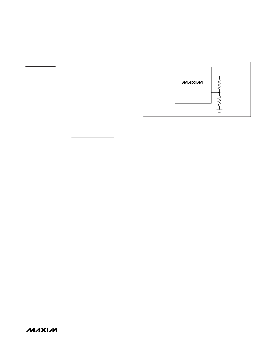
Open-Load Threshold Selection
For the MAX16913A, a resistive divider between REF,
OLT, and GND sets the open-load threshold. See
Figure 3.
Use the following formula to set the desired open-load
threshold:
where I
OL
is the desired open-load current threshold;
A
V
is the current-sense amplifier gain (13V/V typ), and
V
REF
is the reference voltage (+3V typ). The sum of R
1
and R
2
should be large enough so that the output
impedance of the internal reference (5kΩ) is negligible
compared to the sum of R
1
and R
2
, and has a minimum
effect on the accuracy of the adjusted open-load
threshold.
For example, to set the open-load threshold at 10mA,
using a 1Ω sense resistor, use the following method to
calculate the value of R
1
and R
2
:
Choose R
1
= 470kΩ and calculate R
2
as 101kΩ.
Input Capacitor
Connect a low-leakage ceramic capacitor from IN to
GND to limit the input voltage drop during momentary
output short-circuit conditions, and to protect the
device against transients due to inductance in the IN
line. For example, use at least a 0.1µF ceramic capaci-
tor if the input inductance (including any stray induc-
tance) is estimated to be 20µH. Larger capacitor values
reduce the voltage undershoot at the input.
Output Capacitor
In an analogous fashion to the input capacitor, an out-
put capacitor protects the device against transients
due to any series inductance in the output. Under no
conditions should the OUT pin voltage go below -0.3V
as specified in the
Absolute Maximum Ratings
. If a
capacitor alone is not sufficient to avoid large negative
transients on OUT, then a Schottky diode should be
used to clamp transients which go below ground. With
a 100µH output series inductor, a 220µF output capaci-
tor is needed to eliminate potential problems. With larg-
er inductor values or smaller capacitors, a Schottky
clamp diode will be necessary.
Layout and Thermal Dissipation
To optimize the switch response time to output short-
circuit condition, it is very important to keep all traces
as short as possible to reduce the effect of undesirable
parasitic inductance. Place input and output capacitors
as close as possible to the device (no more than 5mm).
R (k )
(R +R )(k )
(1
(V/V))+ 0.4V
3(V)
0.177
2
1
2
Ω
Ω
Ω
=
Ч
Ч
=
( )
.
( )
0 01
13
A
R (k )
(R +R )(k )
(R
I
(V/V))+ 0.4V
V
(V)
2
1
2
SENSE
OL
V
REF
Ω
Ω
Ω
=
Ч
Ч
( )
( )
A
A
R
V
(V)
I
(A)
SENSE
DIFF(MIN)
LOAD(FULL-SCALE)
( )
Ω =
MAX16913
REF
OLT
R
1
R
2
Figure 3. Open-Load Threshold Selection