Pin description – Rainbow Electronics MAX16913A User Manual
Page 5
MAX16913/MAX16913A
Remote Antenna Current-Sense
Amplifier and Switches
_______________________________________________________________________________________
5
Pin Description
PIN
NAME
FUNCTION
1, 8, 9, 16
GND
Ground
2
IN
Input Voltage. Bypass IN to GND with a low-ESR ceramic capacitor with a minimum value of 0.1µF.
3, 4
SENS
Input to Current-Sense Amplifier. Connect the sense resistor between SENS and IN.
5, 6
OUT
Switch Output
7
SHDN
Active-High Control Input. Drive SHDN low to turn on the device.
10
N.C.
No Connection. Not internally connected.
11
OLT
Open-Load Threshold Setting Input. A resistive divider between REF, OLT, and GND sets the open-load
current threshold (MAX16913A). For the MAX16913, connect OLT to GND.
12
REF
+3V Nominal Reference Output. Use a resistive divider between REF, OLT, and ground to set the open-load
current threshold (MAX16913A). The output impedance of this voltage regulator is 5k
Ω.
13
AOUT
Current-Monitor Voltage Output. AOUT can be used to measure the load current by means of an external
ADC. The output impedance is 5k
Ω.
14
OL
Open-Drain Open-Load Indicator Output.
OL goes low when the load current is lower than the open-load
current threshold, or when there is a short-to-battery fault. Connect
OL to a 10k
Ω pullup resistor. See Table 1.
15
SC
Open-Drain Short-Circuit Indicator Output.
SC goes low when the load current is greater than the short-circuit
current threshold or when there is a short-to-battery fault. Connect
SC to a 10k
Ω pullup resistor. See Table 1.
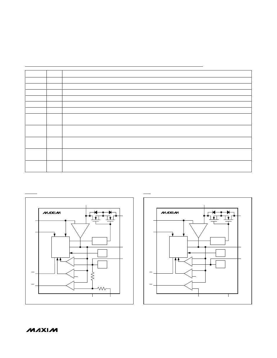
OLT
REF
AOUT
FET
DRIVER AND
CONTROL
REF
OT
OUT
CURRENT
SENSE
SENS
IN
SHDN
CHARGE
PUMP
MAX16913
GND
OL
SC
V
REF2
V
REF
MAX16913 Functional Diagram
OLT
REF
AOUT
FET
DRIVER AND
CONTROL
REF
OT
OUT
CURRENT
SENSE
SENS
IN
SHDN
CHARGE
PUMP
MAX16913A
GND
OL
SC
V
REF2
V
REF
MAX16913A Functional Diagram