Config_ register (0ch–0fh) – Rainbow Electronics MAX11043 User Manual
Page 21
MAX11043
4-Channel, 16-Bit, Simultaneous-Sampling ADCs
with PGA, Filter, and 8-/12-Bit Dual-Stage DAC
______________________________________________________________________________________
21
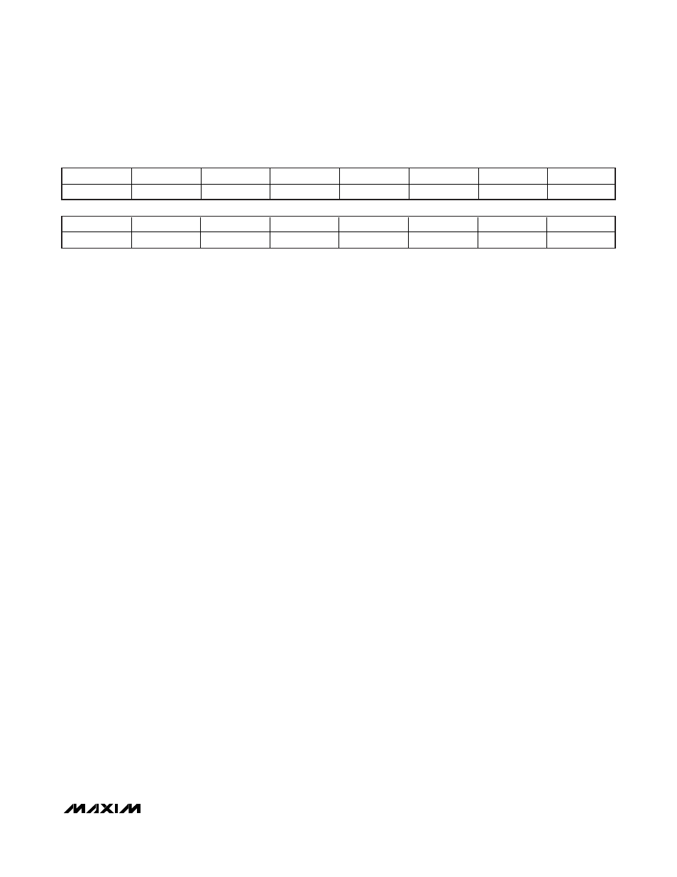
BIT 15
BIT 14
BIT 13
BIT 12
BIT 11
BIT 10
BIT 9
BIT 8
X
X
X
BDAC3
BDAC2
BDAC1
BDAC0
DIFF
CONFIG_ Register (0Ch–0Fh)
This register sets the gain of each ADC channel and
selects one of the default filters or EQ function.
X<15:13>: Don’t-care bits.
BDAC3:BDAC0<12:9>: Sets the input bias voltage for
AC-coupled signals when ENBIAS_ is set to 1.
0000 = 33% of AVDD.
0001 = 35% of AVDD.
0010 = 38% of AVDD.
0011 = 40% of AVDD.
0100 = 42% of AVDD.
0101 = 44% of AVDD.
0110 = 46% of AVDD.
0111 = 48% of AVDD.
1000 = 50% of AVDD.
1001 = 52% of AVDD.
1010 = 54% of AVDD.
1011 = 56% of AVDD.
1100 = 58% of AVDD.
1101 = 60% of AVDD.
1110 = 62% of AVDD.
1111 = 65% of AVDD.
DIFF<8>: Input mode select bit.
1 = normal operation in all modes.
0 = use for a 2x input signal range in LP, gain = 1
mode. Note that THD degrades.
EQ<7>: EQ function.
1 = analog EQ enabled.
0 = analog EQ disabled (default).
MODG1:MODG0<6:5>: ADC modulator gain.
00 = 1 (default).
01 = 2.
10 = 4.
11 = 4.
PDPGA<4>: PGA power-down control.
1 = PGA powered down, gain = 1.
0 = PGA powered, PGA gain set by PGAG (default).
FILT<3>: Programmable filter select.
1 = use preprogrammed LP filter.
0 = use preprogrammed EQ filter (default).
PGAG<2>: High PGA gain setting.
1 = PGA, gain = 16.
0 = PGA, gain = 8 (default).
ENBIASP<1>: Positive input bias enable. Bias voltage
set by BDAC3:BDAC0.
1 = selfbiasing enabled.
0 = selfbiasing disabled (default).
ENBIASN<0>: Negative input bias enable. Bias volt-
age set by BDAC3:BDAC0.
1 = selfbiasing enabled.
0 = selfbiasing disabled (default).
BIT 7
BIT 6
BIT 5
BIT 4
BIT 3
BIT 2
BIT 1
BIT 0
EQ
MODG1
MODG0
PDPGA
FILT
PGAG
ENBIASP
ENBIASN