Detailed description, Analog-to-digital converter, Sinc 5 filter – Rainbow Electronics MAX11043 User Manual
Page 12: Config_ register (0ch–0fh)
MAX11043
4-Channel, 16-Bit, Simultaneous-Sampling ADCs
with PGA, Filter, and 8-/12-Bit Dual-Stage DAC
12
______________________________________________________________________________________
Detailed Description
The MAX11043 features 4 single-ended or differential
channels of simultaneous-sampling ADCs with 16-bit
resolution. The MAX11043 contains a versatile filter
block and PGA per channel. The filter consists of seven
cascaded 2nd-order filter sections for each channel
allowing the construction of a 14th-order filter. The filter
coefficients are user-programmable. Configure each
2nd-order filter as a LP filter, HP filter, or BP filter with
optional rectification. Gain and phase mismatch of the
analog signal path is better than -50dB.
The ADCs can sample up to 800ksps per channel. A
40MHz serial interface provides communication to and
from the device. The SPI interface provides throughput
of 1600ksps; 4 channels at 400ksps per channel or 2
channels at 800ksps per channel. A software-selec-
table scan mode allows reading the ADC results while
simultaneously updating the DAC. Other features of the
MAX11043 include an internal (+2.5V) or external
(+2.0V to +2.8V) reference, power-saving modes, and
a PGA with gains of 1 to 64. The PGA includes an EQ
function that automatically boosts low-amplitude, high-
frequency signals for applications such as CW-chirp
radar.
The MAX11043 includes two 8-bit coarse DACs that set
the high and low references for a second-stage 12-bit
fine DAC, typically used for VCO control. Use software
controls to set the DAC, or step the DAC up and down
using hardware control in programmable steps.
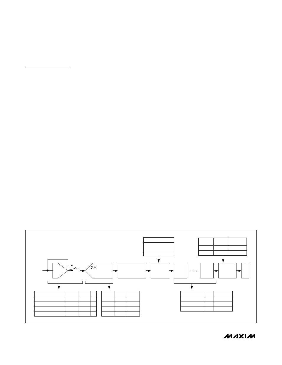
MAX11043 Signal Path
Each of the 4 ADC channels features a PGA and filter
block that feeds the signal to the sigma-delta modula-
tor. The PGA can either be bypassed, which provides a
gain of 1, set to a gain of 8, a gain of 16, or set to ana-
log EQ mode. For more amplification, set the ADC mod-
ulator gain to one, two, or four. After the modulator, the
result passes through the sinc 5 filter and decimator.
Seven biquad programmable digital filters isolate the
band of interest. Read the result using the 40MHz SPI
interface. See Figure 1.
Analog-to-Digital Converter
The MAX11043 features a quad sigma-delta ADC archi-
tecture with 4 differential input channels. For single-
ended operation, connect the N input to the
common-mode voltage or bypass to AGND with a 10µF
capacitor. All inputs feature a programmable bias gen-
erator; see the
CONFIG_ Register (0Ch–0Fh)
section.
All four ADCs convert simultaneously with a maximum
modulator sampling rate of 9.6Msps; decimated by 12
or 24 for output rates of 800ksps and 400ksps, respec-
tively. The SPI bus limits the maximum output data rate
to 40Mbps.
Sinc 5 Filter
The sinc 5 filter removes high-frequency noise from the
output of the sigma-delta modulator. It also decimates
the modulator data by a factor of 12, providing a maxi-
mum of 800ksps to the programmable filters when the
modulator is operating at 9.6Msps. Figure 2 shows the
frequency characteristics of the sinc 5 filter with the
modulator running at 9.6Msps. Operating the modulator
PGA AND
FILTER
MODULATOR
WITH GAINS OF
1, 2, OR 4
SINC 5 FILTER AND
DECIMATE BY 12
SPI
BIQUAD
FILTER 1
BIQUAD
FILTER 7
IN
7 BIQUAD FILTERS IN SERIES
MODG1
MODG0
0
0
0
1
1
0
1
1
GAIN
1
2
4
4
EQUALIZER
LP FILTER AND GAIN 16X
LP FILTER AND GAIN 8X
BYPASS
PGA AND FILTER MODES
PDPGA
PGAG
EQ
1
X
X
0
0
0
0
1
0
0
X
1
FINE
GAIN
ADJUST
CHAN X FINE GAIN
RESOLUTION = 16 BITS
RAM
POR VALUES
POR VALUES
USER VALUES
USER DEFINED
EQUALIZER
LP FILTER
BIQUAD MODES
FILT
1
0
X
RANGE: -4 TO +4
DECIMATE
BY 1 OR 2
DECIMATE
TOTAL
DECIMATION
2
24
1
12
DECSEL
0
1
Figure 1. Signal Path