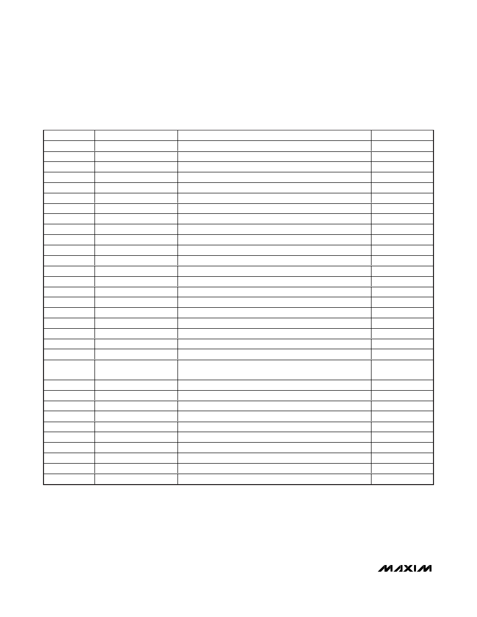
Table 1. spi register map – Rainbow Electronics MAX11043 User Manual
Page 18
MAX11043
4-Channel, 16-Bit, Simultaneous-Sampling ADCs
with PGA, Filter, and 8-/12-Bit Dual-Stage DAC
18
______________________________________________________________________________________
ADDRESS
REGISTER NAME
FUNCTION
BITS
00h
ADCA
ADC channel A result register
16/24
01h
ADCB
ADC channel B result register
16/24
02h
ADCC
ADC channel C result register
16/24
03h
ADCD
ADC channel D result register
16/24
04h
ADCAB
ADC channels A and B results register
32/48
05h
ADCCD
ADC channels C and D results register
32/48
06h
ADCABCD
ADC channels A, B, C, and D results register
64/96
07h
Status
Status register
8
08h
Configuration
Configures the device
16
09h
DAC
Fine DAC value
16
0Ah
DACSTEP
Step size for DAC increment/decrement function
16
0Bh
DACH/DACL
High and low coarse DAC values
8 + 8
0Ch
ConfigA
ADC channel A configuration
16
0Dh
ConfigB
ADC channel B configuration
16
0Eh
ConfigC
ADC channel C configuration
16
0Fh
ConfigD
ADC channel D configuration
16
10h
Reference/Delay
Sets the operation state of the reference and buffers
16
11h
AGain
Channel A fine gain
16
12h
BGain
Channel B fine gain
16
13h
CGain
Channel C fine gain
16
14h
DGain
Channel D fine gain
16
15h
Filter coefficient address
Selects the filter coefficient to read or write. This autoincrements
each time the coefficient data register is accessed.
8
16h
Filter coefficient data out
Coefficient RAMs output data
32
17h
Filter coefficient data in
Filter coefficient data
32
18h
Flash mode
Flash mode selection register
8
19h
Flash addr
Flash address register
16
1Ah
Flash data in
Flash data in register
16
1Bh
Flash data out
Flash data out register
16
1Ch
Reserved
—
—
1Dh
Reserved
—
—
1Eh
Reserved
—
—
1Fh
Reserved
—
—
Register Map
Table 1. SPI Register Map