Rainbow Electronics MAX5172 User Manual
Page 12
MAX5170/MAX5172
Low-Power, Serial, 14-Bit DACs
with Voltage Output
12
______________________________________________________________________________________
User-Programmable Logic Output (UPO)
The UPO allows control of an external device through
the serial interface, thereby reducing the number of
microcontroller I/O pins required. During power-down,
this output retains its digital state prior to shutdown.
When
CLR is pulled low, UPO resets to its programmed
default state. See Table 1 for specific commands to
control the UPO.
Reset (RS) and Clear (
CLR)
The MAX5170/MAX5172 offers a clear pin which resets
the output voltage. If RS = DGND, then
CLR resets the
output voltage to the minimum voltage (0 if OS =
AGND). If RS = V
DD
, then
CLR resets the output volt-
age to midscale. In either case,
CLR resets UPO to its
programmed default state.
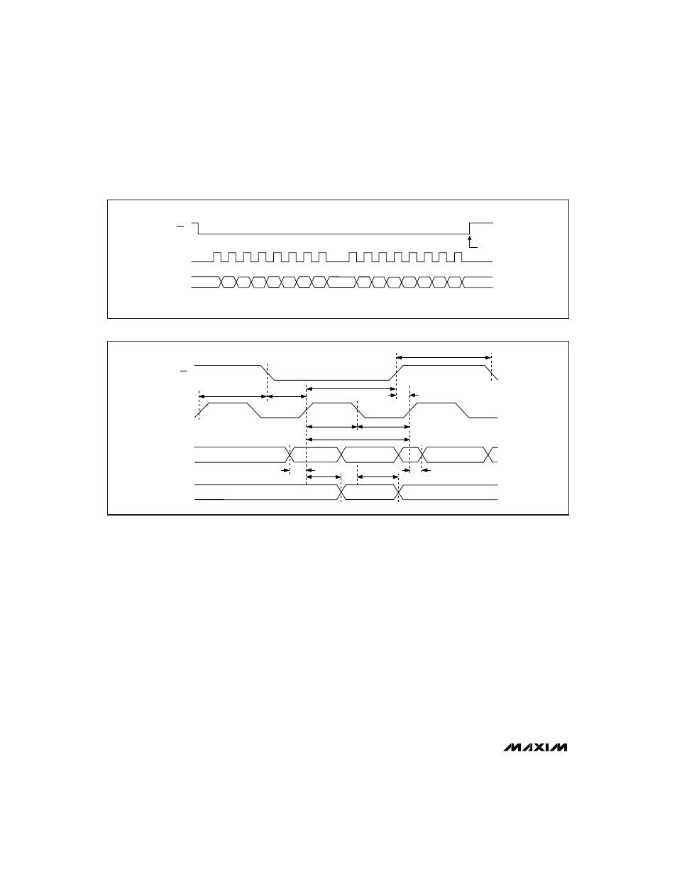
CS
SCLK
DIN
COMMAND
EXECUTED
9
8
16
1
C1
C2
S0
C0
D9
D8
D7
D6
D3
D2
D1
D0
S2
S1
D5
D4
Figure 4. Serial-Interface Timing Diagram
CS
SCLK
DIN
DOUT
t
CSW
t
CS1
t
CSH
t
CSS
t
CSO
t
D02
t
CH
t
CL
t
CP
t
D01
t
DS
t
DH
Figure 5. Detailed Serial-Interface Timing Diagram