Tft-lcd step-up dc-dc converter, Applications information, Table 1. component list – Rainbow Electronics MAX17062 User Manual
Page 8: Table 2. component suppliers
MAX17062
Soft-Start
The MAX17062 can be programmed for soft-start upon
power-up with an external capacitor. When the shutdown
pin is taken high, the soft-start capacitor (C
SS
) is immedi-
ately charged to 0.4V. Then the capacitor is charged at a
constant current of 4μA (typ). During this time, the SS
voltage directly controls the peak inductor current, allow-
ing 0A at V
SS
= 0.4V to the full current limit at V
SS
= 1.5V.
The maximum load current is available after the soft-start
is completed. When the SHDN pin is taken low, the soft-
start capacitor is discharged to ground.
Frequency Selection
The MAX17062’s frequency can be user selected to
operate at either 640kHz or 1.2MHz. Connect FREQ to
AGND for 640kHz operation. For a 1.2MHz switching
frequency, connect FREQ to IN. This allows the use of
small, minimum-height external components while
maintaining low output noise. FREQ has an internal
pulldown, allowing the user the option of leaving FREQ
unconnected for 640kHz operation.
Shutdown
The MAX17062 shuts down to reduce the supply cur-
rent to 0.01μA when SHDN is low. In this mode, the
internal reference, error amplifier, comparators, and
biasing circuitry turn off, and the n-channel MOSFET is
turned off. The step-up regulator’s output is connected
to IN by the external inductor and rectifier diode.
Thermal-Overload Protection
Thermal-overload protection prevents excessive power
dissipation from overheating the MAX17062. When the
junction temperature exceeds T
J
= +160°C, a thermal
sensor immediately activates the fault protection, which
shuts down the MAX17062, allowing the device to cool
down. Once the device cools down by approximately
20°C, the MAX17062 starts up automatically.
Applications Information
Step-up regulators using the MAX17062 can be
designed by performing simple calculations for a first
iteration. All designs should be prototyped and tested
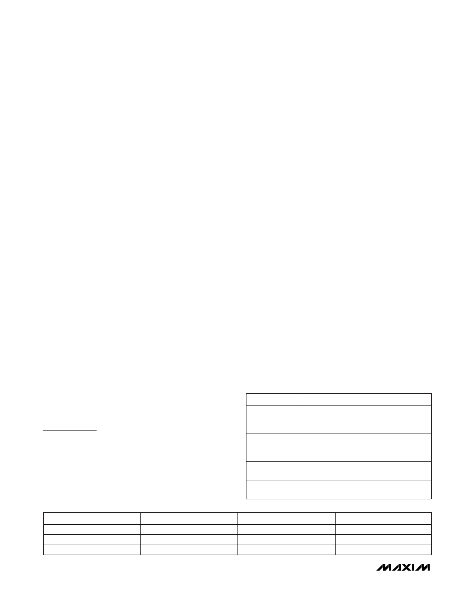
prior to production. Table 1 provides a list of power com-
ponents for the typical applications circuit (Figure 1).
Table 2 lists component suppliers.
External-component-value choice is primarily dictated
by the output voltage and the maximum load current,
as well as maximum and minimum input voltages.
Begin by selecting an inductor value. Once L is known,
choose the diode and capacitors.
Inductor Selection
The minimum inductance value, peak current rating, and
series resistance are factors to consider when selecting
the inductor. These factors influence the converter’s effi-
ciency, maximum output load capability, transient-
response time, and output-voltage ripple. Physical size
and cost are also important factors to be considered.
The maximum output current, input voltage, output volt-
age, and switching frequency determine the inductor
value. Very high inductance values minimize the cur-
rent ripple and therefore reduce the peak current,
which decreases core losses in the inductor and I
2
R
losses in the entire power path. However, large induc-
tor values also require more energy storage and more
turns of wire, which increase physical size and can
increase I
2
R losses in the inductor. Low inductance val-
ues decrease the physical size but increase the current
ripple and peak current. Finding the best inductor
involves choosing the best compromise between circuit
efficiency, inductor size, and cost.
The equations used here include a constant LIR, which
is the ratio of the inductor peak-to-peak ripple current
to the average DC inductor current at the full load cur-
rent. The best trade-off between inductor size and cir-
cuit efficiency for step-up regulators generally has an
LIR between 0.3 and 0.5. However, depending on the
TFT-LCD Step-Up DC-DC Converter
8
_______________________________________________________________________________________
DESIGNATION
DESCRIPTION
C1, C2
4.7μF ±10%, 10V X5R ceramic capacitors
(0603)
TDK C1608X5RIA475K
C7, C8
10μF±10%, 25V X5R ceramic capacitors
(1210)
TDK C3225X5RIE106K
D1
3A, 30V Schottky diode (M-Flat)
Toshiba CMS03
L1
2.7μH ±20% power inductor
TOKO FDV0630-2R7M
Table 1. Component List
SUPPLIER
PHONE
FAX
WEBSITE
TDK
847-803-6100
847-390-4405
www.component.tdk.com
TOKO
847-297-0070
847-699-7864
www.tokoam.com
Toshiba
949-455-2000
949-859-3963
www.toshiba.com/taec
Table 2. Component Suppliers